| SimMechanics | |
Modeling Joints
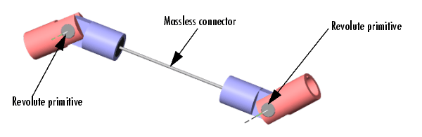
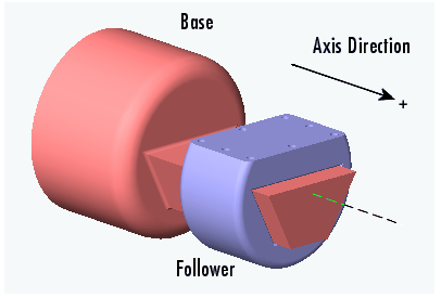
In SimMechanics, a joint represents the degrees of freedom (DoFs) that one body (the follower) has relative to another body (the base). The base body can be a finite rigid body or a ground. Unlike a physical joint, a SimMechanics joint has no mass, although some joints have spatial extension (see the Modeling with Massless Connectors section).
A SimMechanics joint does not necessarily imply a physical connection between two bodies. For example, a SimMechanics Six-DoF joint allows the follower, e.g., an airplane, unconstrained movement relative to the base, e.g., ground, and does not require that the follower ever come into contact with the base.
SimMechanics joints only add degrees of freedom to a machine, because the Body blocks carry no degrees of freedom. Contrast this with physical joints, which both add DoFs (with axes of motion) and remove DoFs (by connecting bodies). See Counting Degrees of Freedom later in this chapter.
SimMechanics provides an extensive Joints library with blocks for modeling various types of joints. This section explains how to use these blocks.
About Joints
Modeling with Joint blocks requires an understanding of the following key concepts:
Joint Primitives
Each Joint block conceptually represents one or more joint primitives that together specify the degrees of freedom that a follower body has relative to the base body. The following table summarizes the joint primitives found singly or multiply in Joint blocks.
Joint Types
The blocks in the SimMechanics Joints library fall into the following categories:
Others specify abstract combinations of degrees of freedom. For example, the Six-DoF block specifies unlimited motion of the follower relative to the base. The Custom Joint allows you to create joints with any desired combination of rotational and translational degrees of freedom.
See the Assembly Restrictions and Modeling with Disassembled Joints sections.
Joint Axes
Joint blocks define one or more axes of translation or rotation along which or around which a follower block can move in relation to the base block. The axes of a Joint block are the axes defined by its component primitives:
For example, a Planar Joint block combines two prismatic axes and hence defines two axes of translation.
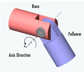
Axis Direction. By default the axes of prismatic and revolute primitives point in the same direction as the z-axis of the World coordinate system. A Joint block's dialog box allows you to point its prismatic and revolute axes in any other direction (see Directing Joint Axes).
Axis Order. SimMechanics executes the motion of composite joints one joint primitive at a time. A joint that defines more than one axis of motion also defines the order in which the follower body moves along each axis or about a pivot. The order in which the axes and/or pivot appear in the Joint block's dialog box is the order in which the follower body moves.
Different primitive execution orders are physically equivalent, unless the joint includes one spherical or three revolute primitives. Pure translations and pure two-dimensional rotations are independent of primitive ordering.
Joint Directionality
Directionality is a property of a joint that determines the dependence of the joint on the sign of forces or torques applied to it. A joint's directionality also determines the sign of signals output by sensors attached to the joint. SimMechanics assigns a directionality to every joint in your model. You must be able to determine the directionality of a joint in order to actuate it correctly and to interpret the output of sensors attached to it.
When assigning directionality to a joint, SimMechanics regards the joint's follower as moving relative to the joint's base. SimMechanics then assigns a directionality to the joint, taking into account the type of joint and the direction of the joint's axis, as follows.
Directionality of a Prismatic Joint. If the joint is prismatic, a positive force applied to the joint moves the follower in the positive direction along the axis of translation. A sensor attached to the joint outputs a positive signal if the follower moves in a positive direction along the joint's axis of translation relative to the base.
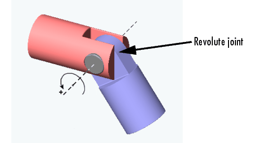
Directionality of a Revolute Joint. If the joint is revolute, a positive torque applied to the joint rotates the follower by a positive angle around the joint's axis of rotation, as determined by the right-hand rule. A sensor attached to the revolute joint outputs a positive signal if the follower rotates by a positive angle around the joint's axis of revolution, as determined by the right-hand rule.
Directionality of a Spherical Joint. Spherical joint directionality means the positive sense of rotation of the three rotational DoFs. Pick a rotation axis, rotating using the right-hand rule from the base Body CS axes. Then rotate the follower Body about that axis in the right-handed sense.
Directionality of Composite Joints. SimMechanics assigns a directionality separately to each joint primitive, based on the primitive's type and the direction of its axis of translation or rotation. In each case, SimMechanics regards the follower body of the composite joint as moving relative to the base body along or around the joint primitive's axis.
The order of primitives in the composite Joint's dialog determines the spatial construction of the joint. The first listed primitive is attached to the base, the second to the first, and so on, down to the follower, which is attached to the last primitive. Moving the first listed primitive moves the subsequent primitives in the list, as well as the follower, relative to the base. Moving any primitive moves the primitives below it in the list (but not those above it), as well as the follower. Moving the last listed primitive moves only the follower.
Changing the Directionality of a Joint. You can change the directionality of a joint by rewiring the Joint block to reverse the roles of the base and follower bodies or by reversing the sign (direction) of the joint axis.
Assembly Restrictions
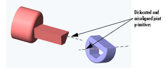
Many joints impose one or more restrictions, called assembly restrictions, on the positions of the bodies that they join. The conjoined bodies must satisfy these restrictions at the beginning of simulation and thereafter within assembly tolerances that you can specify (see Setting Assembly Tolerances in the Running Mechanical Models chapter). For example, the attachment points of revolute and spherical joints must coincide within assembly tolerances; the attachment points of a Prismatic joint must be collinear with the prismatic axis within assembly tolerances; the attachment points of a Planar joint must be coplanar, etc. Composite joints, e.g., the Six-DoF joint, impose assembly restrictions equal to the most restrictive of its joint primitives. See the block reference for each Joint for information on the assembly restrictions, if any, that it imposes. Positioning bodies so that they satisfy a joint's assembly restrictions is called assembling the joint.
All joints except joints in the SimMechanics Disassembled Joints sublibrary require manual assembly. Manual assembly entails your setting the initial positions of conjoined bodies to valid locations (see Assembling Joints). SimMechanics assembles disassembled joints during the model initialization phase of simulation. It assumes that you have already assembled all other joints before the start of simulation. Hence joints that require manual assembly are called assembled joints. During model initialization and at each time step, SimMechanics also checks to ensure that your model's bodies satisfy all assembly restrictions. If any of your model bodies fails to satisfy assembly restrictions, Simulink halts the simulation and displays an error message.
| | Modeling Finite Rigid Bodies | Creating a Joint | |