| SimMechanics | |
Checking Model Validity
Simulink can simulate a SimMechanics model only if it is valid. A model is valid if it satisfies the following rules:
Checking Schematic Topology
To avoid simulation failures, you must ensure that the topology of your block diagram is valid. A block diagram is topologically valid if each schematic that it contains is valid. A schematic is valid if its spanning tree is valid. Thus to determine if your model is valid, first determine the spanning tree of each schematic that it contains and then the validity of the resulting spanning trees.
Determining a Schematic's Spanning Tree
To determine the spanning tree of a schematic, remove all blocks from the schematic except Body and Joint blocks and open every closed loop in the resulting reduced schematic. To open a closed loop, conceptually follow the loop-cutting rules in Cutting Closed Loops.
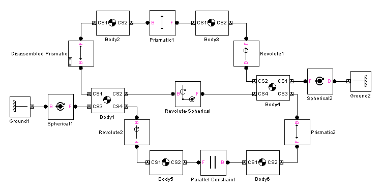
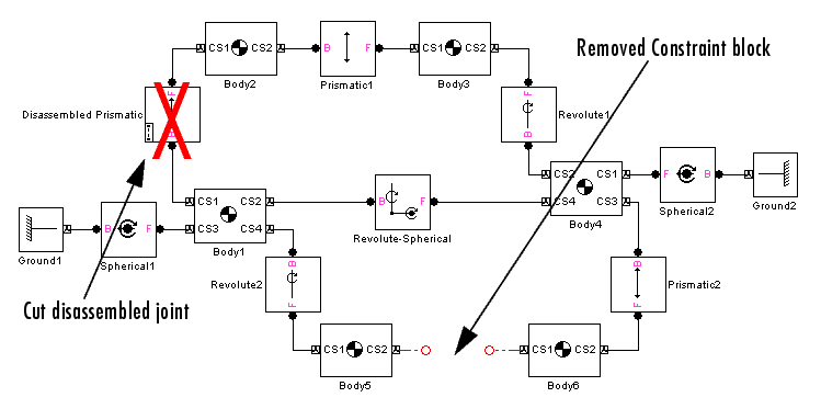
For example, here is a schematic with two closed loops.
Cutting the top loop at the Disassembled Prismatic and removing the Parallel Constraint block (thus simultaneously cutting the bottom loop) yields the schematic's spanning tree.
Determining the Validity of a Spanning Tree
To be valid, a spanning tree must meet the following requirements:
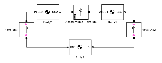
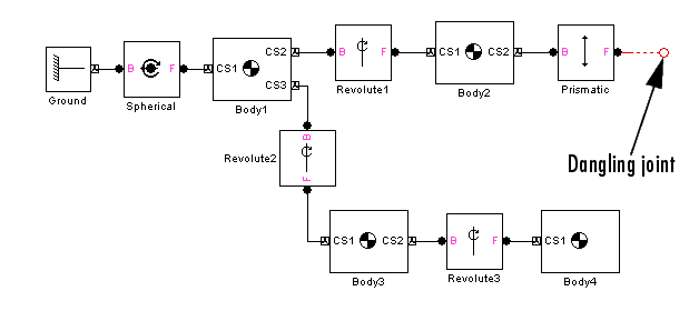
Examples of Invalid Schematic Topologies
Here are some examples of invalid topologies:
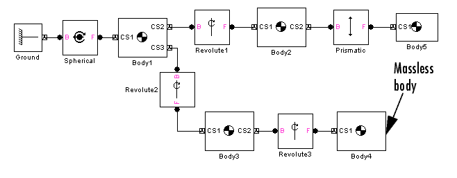
The last two invalid examples are dynamically (but not topologically) equivalent, because a zero-mass body is dynamically no body at all.
Counting Degrees of Freedom
Identifying and counting the independent degrees of freedom (DoFs) of a machine are important for trimming and linearizing SimMechanics models (see Trimming Mechanical Systems and Linearizing SimMechanics Models in the Running Mechanical Models chapter) and for correcting simulation errors (see Troubleshooting Simulation Errors in the Running Mechanical Models chapter).
Your SimMechanics model must have at least one DoF to be valid. A free physical body has six DoFs: three translational and three rotational. But in a machine, connections between bodies by joints, constraints, and drivers, and motion actuation by joint and body actuators reduce the machine's independent DoFs to a smaller number. You also reduce a body's DoFs if you confine the machine's motion to one or two spatial dimensions.
In SimMechanics, a Body block has no DoFs. Connecting Joints to a Body adds DoFs to the machine. The joint primitives represent the body's DoFs relative to other connected Bodies or Grounds. Connecting Constraint and Driver blocks to Bodies or motion-actuating joint primitives in Joints removes DoFs from the machine.
Finding Independent Degrees of Freedom
Here is the formula for determining the number of independent DoFs your model has:
The following three steps define each term on the right-hand side:
# of body DoFs = 6 * (number of Bodies - number of Joints)
| Constraint Block |
Restrictions |
Driver Block |
Restrictions |
| Gear |
One |
Angle |
One |
| Parallel |
Two |
Distance |
One |
| Point-Curve |
Two |
Linear |
One |
| Velocity |
One |
Example: A body is connected to a ground by a single prismatic. You place a constraint on the body that prevents it from moving perpendicularly to the prismatic axis. The body could not move in that direction even if you removed the constraint. So the constraint is redundant, and you would not count it as a motion restriction.
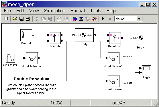
DoF Example: Double Pendulum
The mech_dpen model from the Demos library represents planar double pendulum motion actuated by a Joint Actuator.
The double pendulum has two rigid bodies, such as two rods, confined to move in two dimensions. Ignoring the Joint Actuator temporarily, there are two bodies, two joints, and two revolute primitives, and thus 3 * (2 - 2) + 2 = 2 independent DoFs. There are many ways to represent these two DoFs, but the two revolute primitives are the simplest way.
Including the Joint Actuator in the DoF count removes the revolute primitive in the Revolute block as an independent DoF. So this model actually only has one independent DoF, the revolute primitive in the Revolute1 block.
DoF Example: Four Bar Mechanism
The four bar mechanism of A Four Bar Mechanism in the Learning Basic Procedures chapter has four revolutes. You can establish that only 3 * (3 - 4) + 4 = 1 of these DoFs is actually independent and arrive at the same result obtained in the Four Bar Mechanism example.
| | Modeling Sensors | Running Mechanical Models | |