| SimMechanics | |
Modeling Finite Rigid Bodies
The SimMechanics Body block enables you to model rigid bodies of finite mass and extent. A body is rigid if its internal parts cannot move with respect to one another.
About Body Blocks
A Body block allows you to specify the following attributes of a rigid body.
Mass Properties. These include the body's mass, which determines its response to translational forces, and its inertia tensor, which determines its response to rotational torques.
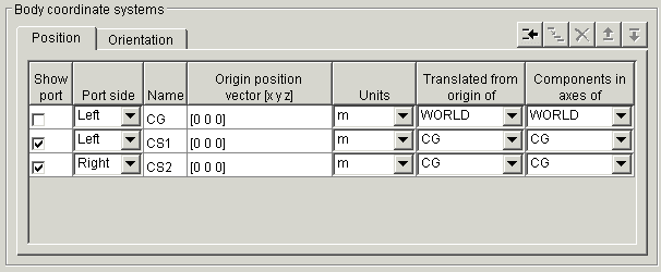
Body Coordinate Systems. By default a Body block defines three local coordinate systems, one associated with a body's center of gravity, labeled CG, and two others, labeled CS1 and CS2, respectively, associated with two other points on the body that you can specify. You can create additional body coordinate systems or delete them as necessary.
A Body block's dialog box allows you to specify a Body CS's origin (see Setting a Body CS's Position) and orientation (see Setting a Body CS's Orientation). The origin and orientation of a body's CG CS specify the body's initial location and orientation. The origins of the other body coordinate systems specify the initial locations of other points on the body.
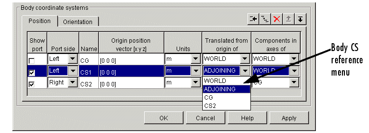
SimMechanics allows flexibility in specifying the origins and orientations of a body's coordinate systems. You can specify the origin and orientation of a body CS relative to
This simplifies creation and maintenance of models. The only limitation is that you must specify the origin and location of at least one of a model's body coordinate systems relative to the World CS.
Connector Ports. Any Body CS can display a Body CS Port. A Body CS Port allows you to attach Joints, Actuators, and Sensors to a Body. By default, a Body's CS1 and CS2 coordinate systems each display a Body CS port. You can display a port for any other Body coordinate system as well, including a Body's CG CS.
Creating a Body Block
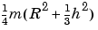
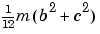
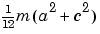
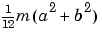
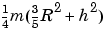
Determining Inertia Tensors for Common Shapes
The following table enables you to determine the inertia tensors for some common shapes. For each shape of mass m, the table lists the shape's principle moments of inertia, I1, I2, and I3, along the x-, y-, and z-axes of the shape's CG coordinate system.
The corresponding inertia tensor for the shape is the following 3-by-3 matrix:

Working with Body Coordinate Systems
Every body in SimMechanics has body coordinate systems (CSs) attached to it. The location of a body CS is the origin of that CS. The CS's rectangular x-y-z coordinate axes are rotated at some orientation. You set up body CS origins and orientations before running your model. But once the bodies start to move, the origins and orientations of a body's CSs remain fixed in the body. The elements of a body's inertia tensor also remain fixed in the body.
The sections Managing Body Coordinate Systems and Creating Body CS Ports explain how to create custom body coordinate systems and Body CS ports or delete existing ports.
Setting a Body CS's Position
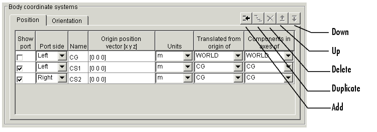
The Position pane of a Body block's dialog box allows you to specify the position of any of a body's local coordinate systems.
The Translated from origin of and Components in axes of lists in the pane together specify which other of your model's coordinate systems you use as reference points and orientations to set up the coordinate systems of the body you are configuring.
To specify the position of a Body CS:
Each row specifies the position of the coordinate system specified in the Name column.
m as the units for specifying CS2's origin and CS1 and WORLD as the origin and orientation of the position specification CS for CS2. Now suppose that you want to specify the location of CS2 as 1 meter to the right of CS1 along the World x-axis. Then you would enter [1 0 0] as CS2's position vector.
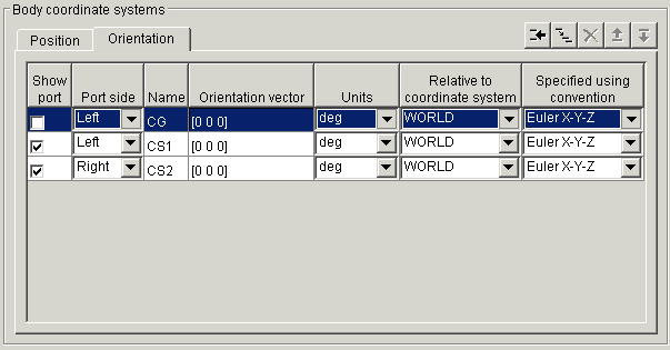
Setting a Body CS's Orientation
The Orientation pane of a Body block's dialog box allows you to specify the orientation of any of a body's local coordinate systems.
To specify the orientation of a Body CS:
Managing Body Coordinate Systems
You will often need to modify the default body coordinate systems of a Body block. You might want to connect a Body to more than two Joints, in which case you need not only more Body CSs, but their Body CS ports as well. Connecting Actuators and Sensors to Bodies requires a Body CS and Body CS port for each connection.
The Body coordinate systems panel of a Body block's dialog box contains a row of buttons that allow you to add, delete, duplicate, and reorder a Body's local coordinate systems.
To use these buttons, select a Body CS in the CS table and select
Creating Body CS Ports
To add or delete a port from a Body block's icon, open the block's dialog box and select or unselect the CS's Show port check box in the dialog box's Body CS table. Click OK or Apply to confirm the change.
| | Modeling Bodies | Modeling Joints | |