
| SimMechanics |   |
Apply classical friction to a joint primitive
Library
Description
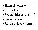
The Joint Stiction Actuator block applies stiction (classical friction) to a prismatic or revolute joint primitive. The stiction is regulated by an idealized model whose parameters you specify. (See Stiction Theory following.) The Joint Stiction Actuator applies stiction to the joint primitive as a relative force/torque between the joint's connected Bodies. The bodies can experience additional forces independent of the joint.
The inports are Simulink signals. The output is a Connector Port. You cannot connect a Joint Stiction Actuator to a Spherical block or spherical primitive. Restrictions on simultaneous actuators and sensors:
External Actuation, you can apply to the joint primitive an external (nonfrictional) force/torque actuation signal equivalent to applying a Joint Actuator.
Dialog Box and Parameters
The dialog box has one active area, Stiction actuation.
Unknown.N (Newtons) if connected to a prismatic primitive and N-m (Newton-meters) if connected to a revolute primitive.N (Newtons) if connected to a prismatic primitive and N-m (Newton-meters) if connected to a revolute primitive.Summary of Joint Stiction Actuator inport signals
All the Simulink inports are 1-component signals. Here is an example of a prismatic joint connected between two bodies and actuated with stiction:
Joint Stiction Actuator Simulink Inport Signals
Units
You specify units in the dialog box only for the external nonfrictional and kinetic friction forces/torques, Fext and FK. These two friction signals are used to integrate the physical motion of the joint and have physical significance in the model context. So units are necessary for Fext and FK.
The other three signals are compared only to one another in the locking condition FSf < Ftest < FSr. These friction signals are not used to integrate motion and thus do not have units set in the dialog box. But they must have the same implicit units for comparison.
| Caution
The threshold velocity vth must be set greater than the Absolute tolerance in the Simulation Parameters dialog box to avoid a meaningless threshold value.
Never set Absolute tolerance to See Choosing Simulation Options for a discussion of setting simulation parameters. |
Example
The mech_dpen_sticky model in the Demos library has two revolute joints actuated with stiction. See Joint Stiction Actuator Example: Mixed Static and Kinetic Friction in the Modeling Mechanical Systems chapter.
Kinematics
v and a are the velocity and acceleration along/around a joint primitive axis. These quantities are relative between the two bodies at the joint ends and signed  to indicate forward or reverse. The joint directionality is set by the base (B)-follower (F) Body sequence of Bodies attached to the joint primitive being actuated.
Continuous Motion
A joint subject to stiction, if unlocked, moves in continuous motion. During this motion, you can apply two forces/torques at the joint primitive:
Discrete Modes: Locked, Wait, Unlocked
Besides its continuous motion state, a joint actuated by stiction has multiple discrete modes. The Joint Stiction Actuator switches a joint primitive between locked and unlocked modes via event detection. In one mode, the joint locks rigidly; in the other, it moves with the kinetic friction and external, nonfrictional forces/torques FK and Fext applied.
You specify the switching event by a two-condition threshold, constructed from four user-specified inputs. (See the following Discrete Joint Stiction Modes and Transition Thresholds figure).
The static test and kinetic frictions Ftest and FK and the threshold velocity vth can be discontinuous, but should be physically sensible.
Locked Mode
In this mode, v and a of the joint are zero. The static computed force/torque FS at the joint is internally computed to maintain this mode: Fext + FS + FF - FB = 0. The forces/torques FB, FF are the forces/torques on the base and follower Bodies apart from those forces/torques acting at the joint.
The mode remains locked as long as FSf < Ftest < FSr.
In most realistic friction models, you would set Ftest equal to the computed FS.
Wait Mode
If the static test friction Ftest leaves the static friction range [FSf, FSr], the joint has passed the first threshold condition for unlocking, and the simulation enters Wait Mode.
A search begins for a mode of this joint consistent with the modes of all other joints. During the search, the net force/torque at the joint primitive F = Fext + FK is computed, where FK is the kinetic friction. If a < 0, the search returns to the Locked Mode. Once consistent modes for all joints are found, the simulation restarts, integrating a to obtain v. When  exceeds vth, the second threshold condition, the joint unlocks.
This mode prevents infinite cycling between Locked and Unlocked Modes, although it can noticeably slow down the simulation. The mode search uses an algebraic loop, which displays warnings at the MATLAB command line.
Unlocked Mode
In the Unlocked Mode, the joint primitive moves, actuated by the sum of the external, non-frictional force/torque Fext and the kinetic friction FK. The joint returns to the Locked Mode if Simulink detects v crossing zero.
Discrete Joint Stiction Modes and Transition Thresholds
See Also
Joint Actuator, Joint Initial Condition Actuator, Joint Sensor, Prismatic, Revolute
See Creating Joints.
In Simulink, see the Signal Routing Library and the Sources Library, and Zero Crossing Detection.
 | Joint Sensor | Linear Driver |  |