| DSP Blockset | |
Generate a swept-frequency cosine (chirp) signal.
Library
Description
The Chirp block outputs a swept-frequency cosine (chirp) signal with unity amplitude and continuous phase. To specify the desired output chirp signal, you must define its instantaneous frequency function, also known as the output frequency sweep. The frequency sweep can be linear, quadratic, or logarithmic, and repeats once every Sweep time by default. See other sections of this reference page for more details about the block.
Sections of This Reference Page
Variables Used in This Reference Page
Setting the Output Frame Status
Use Samples per frame parameter to set the block's output frame status, as summarized in the table. The Sample time parameter sets the sample time of both sample- and frame-based outputs.
| Setting of Samples Per Frame Parameter |
Output Frame Status |
1 |
Sample-based |
n (any integer greater than 1) |
Frame-based, frame size n |
Shaping the Frequency Sweep by Setting Frequency Sweep and Sweep Mode
The basic shape of the output instantaneous frequency sweep, fi(t), is set by the Frequency sweep and Sweep mode parameters, described in the following table.
Parameters for Setting Sweep Shape
Possible Settings
Parameter Description
Frequency sweep
Linear
Quadratic
Logarithmic
Swept cosineDetermines whether the sweep frequencies vary linearly, quadratically, or logarithmically. (Linear and swept cosine sweeps both vary linearly.)
Sweep mode
Unidirectional
BidirectionalDetermines whether the sweep is unidirectional or bidirectional. For details, see Unidirectional and Bidirectional Sweep Modes.
The following diagram illustrates the possible shapes of the frequency sweep that you can obtain by setting the Frequency sweep and Sweep mode parameters.
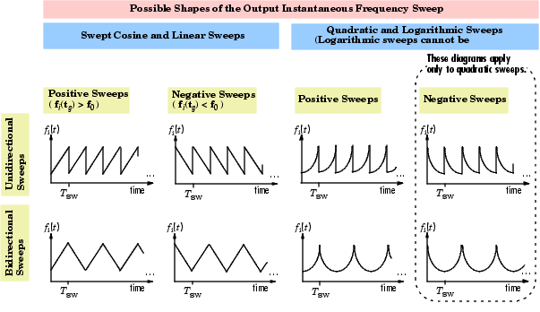
For information on how to set the frequency values in your sweep, see Setting Instantaneous Frequency Sweep Values.
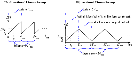
Unidirectional and Bidirectional Sweep Modes
The Sweep mode parameter determines whether your sweep is unidirectional or bidirectional, which affects the shape of your output frequency sweep (see Shaping the Frequency Sweep by Setting Frequency Sweep and Sweep Mode). The following table describes the characteristics of unidirectional and bidirectional sweeps.
| Sweep mode Parameter Settings |
Sweep Characteristics |
| Unidirectional |
|
| Bidirectional |
The following diagram illustrates a linear sweep in both sweep modes. For information on setting the frequency values in your sweep, see Setting Instantaneous Frequency Sweep Values.
Setting Instantaneous Frequency Sweep Values
Set the following parameters to tune the frequency values of your output frequency sweep:
The following table summarizes the sweep values at specific times for all Frequency sweep settings. For information on the formulas used to compute sweep values at other times, see Block Computation Methods.
Block Computation Methods
The Chirp block uses one of two formulas to compute the block output, depending on the Frequency Sweep parameter setting. For details, see the following sections:
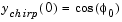
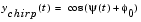
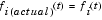
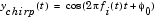
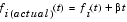
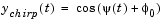
Equations for Output Computation. The following table shows the equations used by the block to compute the user-specified output frequency sweep, fi(t), the block output, ychirp(t), and the actual output frequency sweep, fi(actual)(t). The only time the user-specified sweep is not the actual output sweep is when the Frequency sweep parameter is set to Swept cosine.
| Note The following equations apply only to unidirectional sweeps in which fi(0) < fi(tg). To derive equations for other cases, you may find it helpful to examine the following table and the diagram in Shaping the Frequency Sweep by Setting Frequency Sweep and Sweep Mode. |
Table 7-2 contains the following variables:
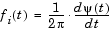
 -- the phase of the chirp signal, where
  , and
, and  is the derivative of the phase
Output Computation Method for Linear, Quadratic, and Logarithmic Frequency Sweeps. The derivative of the phase of a chirp function gives the instantaneous frequency of the chirp function. The Chirp block uses this principle to calculate the chirp output when the Frequency Sweep parameter is set to Linear, Quadratic, or Logarithmic.
|
For instance, if you want a chirp signal with a linear instantaneous frequency sweep, you should set the Frequency Sweep parameter to Linear, and tune the linear sweep values by setting other parameters appropriately. The block will output a chirp signal, the phase derivative of which is the specified linear sweep. This ensures that the instantaneous frequency of the output is the linear sweep you desired. For equations describing the linear, quadratic, and logarithmic sweeps, see Equations for Output Computation.
Output Computation Method for Swept Cosine Frequency Sweep. To generate the swept cosine chirp signal, the block sets the swept cosine chirp output as follows.
|
Note that Equation 7-1 does not hold for the swept cosine chirp, so the user-defined frequency sweep, fi(t), is not the actual output frequency sweep, fi(actual)(t), of the swept cosine chirp. Thus, the swept cosine output may not behave as you expect. To learn more about swept cosine chirp behavior, see Cautions Regarding the Swept Cosine Sweep and Equations for Output Computation.
Cautions Regarding the Swept Cosine Sweep
If you want a linearly swept chirp signal, we recommend you use a linear frequency sweep. Though a swept cosine frequency sweep also yields a linearly swept chirp signal, the output may have unexpected frequency content. For details, see the following two sections.
Swept Cosine Instantaneous Output Frequency at the Target Time is not the Target Frequency. The swept cosine sweep value at the Target time is not necessarily the Target frequency. This is because the user-specified sweep is not the actual frequency sweep of the swept cosine output, as noted in Output Computation Method for Swept Cosine Frequency Sweep. See Table 7-1, Instantaneous Frequency Sweep Values, for the actual value of the swept cosine sweep at the Target time.
Swept Cosine Output Frequency Content May Greatly Exceed Frequencies in the Sweep. In Swept cosine mode, you should not set the parameters so that 1/Tsw is very large compared to the values of the Initial frequency and Target frequency parameters. In such cases, the actual frequency content of the swept cosine sweep may be closer to 1/Tsw, far exceeding the Initial frequency and Target frequency parameter values.
Examples
The first few examples demonstrate how to use the Chirp block's main parameters, how to view the output in the time domain, and how to view the output spectrogram:
Examples 4 and 5 illustrate Chirp block settings that may produce unexpected outputs:
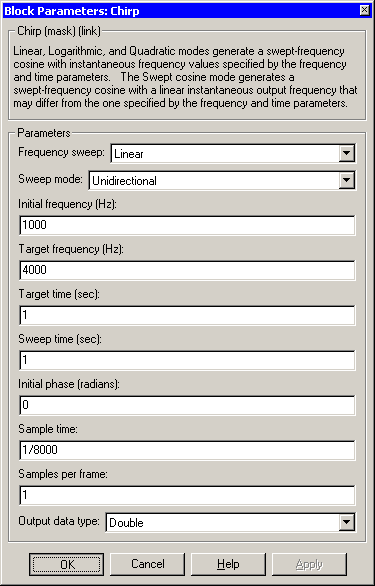
Example 1: Setting a Final Frequency Value for Unidirectional Sweeps. Often times, you may want a unidirectional sweep for which you know the initial and final frequency values. You can specify the final frequency of a unidirectional sweep by setting Target time equal to Sweep time, in which case the Target frequency becomes the final frequency in the sweep. The following model demonstrates this method.
This technique may not work for swept cosine sweeps. For details, see Cautions Regarding the Swept Cosine Sweep.
Open the Example 1 model by clicking here in the MATLAB Help Browser. You can also rebuild the model yourself; see the following list for model parameter settings (leave unlisted parameters in their default states).
Since Target time is set to equal Sweep time (1 second), the Target frequency (25 Hertz) is the final frequency of the unidirectional sweep.
Run your model to see the time domain output, and then type the following command to view the chirp output spectrogram.
specgram(dsp_examples_yout,[0:.01:40],400,hamming(128),110)
Example 2: Bidirectional Sweeps. Change the Sweep mode parameter in the Example 1 model to Bidirectional, and leave all other parameters the same to view the following bidirectional chirp. Note that in the bidirectional sweep, the period of the sweep is twice the Sweep time (2 seconds), whereas it was one Sweep time (1 second) for the unidirectional sweep in Example 1.
Open the Example 2 model by clicking here in the MATLAB Help Browser.
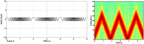
Run your model to see the time domain output, and then type the following command to view the chirp output spectrogram.
Example 3: When Sweep Time is Greater Than Target Time. Setting Sweep time to 1.5 and leaving the rest of the parameters as in the Example 1 model gives the following output. The sweep still reaches the Target frequency (25 Hertz) at the Target time (1 second), but since Sweep time is greater than Target time, the sweep continues on its linear path until one Sweep time (1.5 seconds) is traversed.
Unexpected behavior may arise when you set Sweep time greater than Target time; see Example 4: Output Sweep with Negative Frequencies for details.
Open the Example 3 model by clicking here in the MATLAB Help Browser.
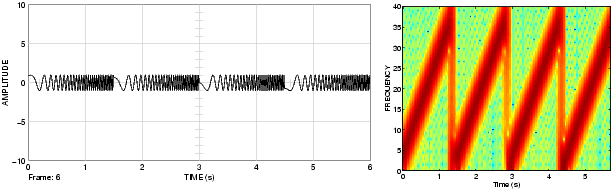
Run your model to see the time domain output, and then type the following command to view the chirp output spectrogram.
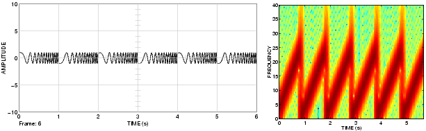
Example 4: Output Sweep with Negative Frequencies. Modify the Example 1 model by changing Sweep time to 1.5, Initial frequency to 25, and Target frequency to 0. The output chirp of this example may not behave as you expect because the sweep contains negative frequencies between 1 and 1.5 seconds. The sweep reaches the Target frequency of 0 Hertz at one second, then continues on its negative slope, taking on negative frequency values until it traverses one Sweep time (1.5 seconds).
The spectrogram may reflect negative sweep frequencies along the x-axis so they appear to be positive, as in the one below. If you unexpectedly get a chirp output with a spectrogram resembling the one following, your chirp's sweep may contain negative frequencies. See the next example for another possible unexpected chirp output.
Open the Example 4 model by clicking here in the MATLAB Help Browser.
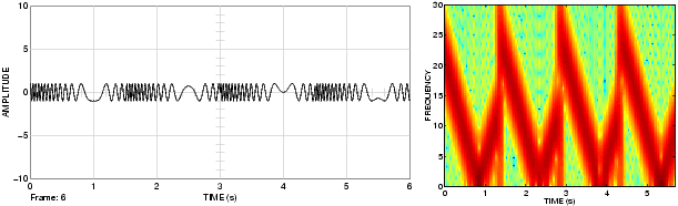
Run your model to see the time domain output, and then type the following command to view the chirp output spectrogram.
Example 5: Output Sweep with Frequencies Greater Than Half the Sampling Frequency. Modify the Example 1 model by changing the Target frequency parameter to 275. The output chirp of this model may not behave as you expect because the sweep contains frequencies greater than half the sampling frequency (200 Hertz), which causes aliasing. If you unexpectedly get a chirp output with a spectrogram resembling the one following, your chirp's sweep may contain frequencies greater than half the sampling frequency. See the previous example for another possible unexpected chirp output.
Open the Example 5 model by clicking here in the MATLAB Help Browser.
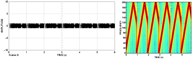
Run your model to see the time domain output, and then type the following command to view the chirp output spectrogram.
Dialog Box
 . Tunable.
 . Tunable.
 , of the cosine output at t=0;
  . Tunable.
Supported Data Types
To learn how to convert to the above data types in MATLAB and Simulink, see Supported Data Types and How to Convert to Them.
See Also
| Signal From Workspace |
DSP Blockset |
| Signal Generator |
Simulink |
| Sine Wave |
DSP Blockset |
chirp |
Signal Processing Toolbox |
specgram |
Signal Processing Toolbox |
Also see the following topics:
| | Check Signal Attributes | Cholesky Factorization | |


 -- the Initial phase parameter value, where