
| DSP Blockset |   |
Find the maximum values in an input or sequence of inputs.
Library
Description
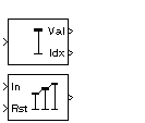
The Maximum block identifies the value and position of the largest element in each column of the input, or tracks the maximum values in a sequence of inputs over a period of time. The Mode parameter specifies the block's mode of operation and can be set to Value, Index, Value and Index, or Running.
Value Mode
When Mode is set to Value, the block computes the maximum value in each column of the M-by-N input matrix u independently at each sample time.
For convenience, length-M 1-D vector inputs and sample-based length-M row vector inputs are both treated as M-by-1 column vectors.
The output at each sample time, val, is a 1-by-N vector containing the maximum value of each column in u. For complex inputs, the block selects the value in each column that has the maximum magnitude, max(abs(u)), as shown below.
The frame status of the output is the same as that of the input.
Index Mode
When Mode is set to Index, the block computes the maximum value in each column of the M-by-N input matrix u,
and outputs the sample-based 1-by-N index vector, idx. Each value in idx is an integer in the range [1 M] indexing the maximum value in the corresponding column of u. When inputs to the block are double-precision values, the index values are double-precision values. Otherwise, the index values are 32-bit unsigned integer values.
As in Value mode, length-M 1-D vector inputs and sample-based length-M row vector inputs are both treated as M-by-1 column vectors.
If a maximum value occurs more than once in a particular column of u, the computed index corresponds to the first occurrence. For example, if the input is the column vector [3 2 1 2 3]', the computed index of the maximum value is 1 rather than 5.
Value and Index Mode
When Mode is set to Value and Index, the block outputs both the vector of maxima, val, and the vector of indices, idx.
Running Mode
When Mode is set to Running, the block tracks the maximum value of each channel in a time-sequence of M-by-N inputs. For sample-based inputs, the output is a sample-based M-by-N matrix with each element yij containing the maximum value observed in element uij for all inputs since the last reset. For frame-based inputs, the output is a frame-based M-by-N matrix with each element yij containing the maximum value observed in the jth column of all inputs since the last reset, up to and including element uij of the current input.
As in the other modes, length-M 1-D vector inputs and sample-based length-M row vector inputs are both treated as M-by-1 column vectors.
Resetting the Running Maximum. The block resets the running maximum whenever a reset event is detected at the optional Rst port. The rate of the reset signal must be a positive integer multiple of the rate of the data signal input.
For sample-based inputs, a reset event causes the running maximum for each channel to be initialized to the value in the corresponding channel of the current input. For frame-based inputs, a reset event causes the running maximum for each channel to be initialized to the earliest value in each channel of the current input.
The reset event is specified by the Reset port menu, and can be one of the following:
Rst port.
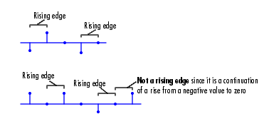
Rst input does one of the following:

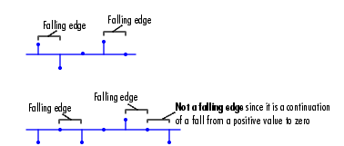
Rst input does one of the following:

Rst input is a Rising edge or Falling edge (as described above).
Rst input is not zero.
| Note When running simulations in the Simulink MultiTasking mode, sample-based reset signals have a one-sample latency, and frame-based reset signals have one frame of latency. Thus, there is a one-sample or one-frame delay between the time the block detects a reset event, and when it applies the reset. For more information on latency and the Simulink tasking modes, see Excess Algorithmic Delay (Tasking Latency) and the topic on the Simulation Parameters dialog box in the Simulink documentation. |
Example
The Maximum block in the model below calculates the running maximum of a frame-based 3-by-2 (two-channel) matrix input, u. The running maximum is reset at t=2 by an impulse to the block's Rst port.
The Maximum block has the following settings:
The Signal From Workspace block has the following settings:
The Discrete Impulse block has the following settings:
The block's operation is shown in the figure below.
The statsdem demo illustrates the operation of several blocks from the Statistics library.
Dialog Box
Rst input port when Running is selected as the Mode parameter. The rate of the reset signal must be a positive integer multiple of the rate of the data signal input. For information about the options for this parameter, see Resetting the Running Maximum.Supported Data Types
Rst port.
To learn how to convert to the above data types in MATLAB and Simulink, see Supported Data Types and How to Convert to Them.
See Also
| Mean |
DSP Blockset |
| Minimum |
DSP Blockset |
| MinMax |
Simulink |
max |
MATLAB |
Also see Statistics for a list of all the blocks in the Statistics library.
 | Matrix Viewer | Mean |  |