| Robust Control Toolbox | |
Syntax
[af,bf,cf,df,svl] = ltru(A,B,C,D,Kc,Xi,Th,r,w)
[af,bf,cf,df,svl] = ltry(A,B,C,D,Kf,Q,R,q,w)
[ssf,svl] = ltru(ss,Kc,Xi,Th,r,w,svk)
[ssf,svl] = ltry(ss,Kf,Q,R,q,w,svk)
Description
Given a plant with transfer function 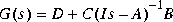 ,
, ltru implements the Doyle-Stein procedure for recovering full-state-feedback loop transfer function 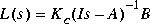
via a Kalman-filter-reconstructed state feedback with fictitious plant noise. Singular-value Bode plots of the reconstructed-state loop transfer function matrix

are computed and displayed for each value of the fictitious noise intensity parameter r, so that you can observe the loop-transfer recovery as r increases,
ss = optional system matrix form
Kc -- full-state feedback gain matrix
Xi -- nominal plant noise intensity
Th -- measurement noise intensity
r -- row vector of intensities of fictitious plant noise
The row vector r contains a set of "recovery" gains (e.g.,  ).
). ltru will iteratively compute the singular-value Bode plot of the loop gain F(s)G(s) and plot the associated curves in front of the user, until the gain vector r runs out of its entries.
The controller F(s) corresponding to the last value of r is returned in state-space (af,bf,cf,df). All the singular values (MIMO case) or the Nyquist loci (SISO case) will be returned in variable svl. The frequency response of L(j ) is stored in
 svk which can be passed into ltru as an optional input and displayed superimposed on the frequency plots of Lr(j).
ltry does the "dual" problem, i.e., recovery of the observer loop transfer function 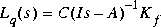
Examples
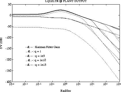
Consider the fighter design example in [2]. Apply the LTR procedure ltry to the plant model, and let the observer be a Kalman-Bucy filter.
The initial cost and recovery gains used in this example are
The singular value Bode plot is shown in Figure 1-13.
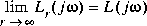
The LQG/LTR loop transfer function converges in the limit (as q increases to  ) to C (Is - A)-1 Kf, which is the KBF loop transfer function.
Algorithm
The controller F(s) is computed as

ltru, the Kalman filter gain is 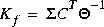 and
and  satisfies the Kalman filter Riccati equation
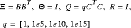
In ltry gain Kc is computed as  where P satisfies the full-state Riccati equation
The theory is documented in [1].
Figure 1-13: Example of LQG/LTR at Plant Output.
Limitations
The ltru procedure may fail for nonminimum phase plants or for plants with number of control inputs exceeds the number of measurement outputs. The dual procedure ltry may fail for nonminimum phase plants or for plants with fewer inputs than outputs.
See Also
h2lqg, hinf, hinfdemo, lqg, ltrdemo
References
[1] J. Doyle and G. Stein "Multivariable Feedback Design: Concepts for a Classical/Modern Synthesis," IEEE Trans. on Automat. Contr., AC-26, pp. 4-16, 1981.
[2] M. G. Safonov, A. J. Laub, and G. Hartmann, "Feedback Properties of Multivariable Systems: The Role and Use of Return Difference Matrix," IEEE Trans. of Automat. Contr., AC-26, pp. 47-65, 1981.
| lqg | mksys, vrsys, issystem | |
 , (the plant)