| SimMechanics |
  |
Bushing
Represent a composite joint with three translational and three rotational DoFs
Library
Joints
Description

The Bushing block represents a composite joint with three translational degrees of freedom (DoFs) as three prismatic primitives and three rotational DoFs as three revolute primitives. There are no constraints among the primitives. Unlike Six-DoF, Bushing represents the rotational DoFs as three revolutes, rather than as one spherical.
| Caution
A joint with three revolute primitives becomes singular if two or three of the rotation axes become parallel ("gimbal lock"). A joint with two or three prismatic primitives becomes singular if two or three of the translation axes become parallel. The simulation stops with errors in these cases.
|
You must connect each side of the Joint block to a Body block at a Body coordinate system (CS) point. The Bushing block is assembled: the origins of these Body CSs must lie along the primitive axes, and the Body CS origins on either side of the Joint must be spatially collocated points, to within assembly tolerances.
You can connect any Joint block to two and only two Body blocks, and Joints have a default of two Connector Ports for connecting to base and follower Bodies.
A Joint block represents only the abstract relative motion of two bodies, not the bodies themselves. You must specify reference CSs to define the directions of the joint axes.
Dialog Box and Parameters

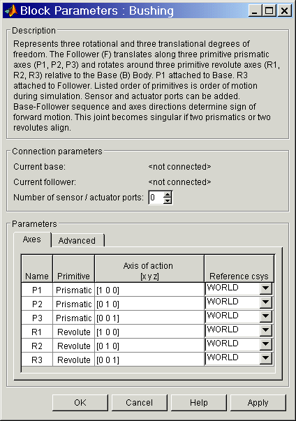
The dialog box has two active areas, Connection parameters and Parameters.
Connection Parameters
- Current base
- When you connect the base (B) Connector Port on the Bushing block to a Body CS Port on a Body, this parameter is automatically reset to the name of this Body CS. See the following Bushing base and follower Body Connector Ports figure.
- The base Body is automatically connected to the first joint primitive
P1 in the primitive list in Parameters.
- Current follower
- When you connect the follower (F) Connector Port on the Bushing block to a Body CS Port on a Body, this parameter is automatically reset to the name of this Body CS. See the following Bushing base and follower Body Connector Ports figure.
- The follower Body is automatically connected to the last joint primitive
R3 in the primitive list in Parameters.
- Number of sensor/actuator ports
- Using this spinner menu, you can set the number of extra Connector Ports needed for connecting Joint Actuator and Joint Sensor blocks to this Joint. The default is
0.
- The motions of prismatic and revolute primitives are specified in linear and angular units, respectively.
The base (B)-follower (F) Body sequence determines the sense of positive motion. Positive translation is the follower moving in the direction of the translation axis. Positive rotation is the follower moving around the rotational axis following the right-hand rule.

Bushing base and follower Body Connector Ports
Parameters
Toggle between the Axes and Advanced panels with the tabs.
The entries on the Axes pane are required. Each DoF primitive in Bushing has an entry line. These lines specify the direction of the axes of action of the DoFs that the Bushing represents.
- Name - Primitive
- The primitive list states the names and types of joint primitives that make up the Bushing block: prismatic primitives
P1, P2, P3, and revolute primitives R1, R2, R3.
- Axis of action [x y z]
- Enter here as a three-component vector the directional axes defining the allowed motions of these primitives and their corresponding DoFs:
- Prismatic: axis of translation
- Revolute: axis of rotation
- The default vectors are shown in the dialog box above. The axis is a directed vector whose overall sign matters.
- To prevent singularities and simulation errors, no two of the revolute axes and no two of the prismatic axes can be parallel.
- Reference csys
- Using the pull-down menu, choose the coordinate system (World, the base Body CS, or the follower Body CS) whose coordinate axes the vector axis of action is oriented with respect to. This CS also determines the absolute meaning of forces/torques and motion along/about the joint axis. The default is
WORLD.
The Advanced pane is optional. You use it to control the way SimMechanics interprets the topology of your schematic diagram.

- Mark as the preferred cut joint
- In a closed loop, one and only one joint is cut during the simulation. SimMechanics does the cutting internally and automatically.
- If you want this particular joint to be weighted preferentially for cutting during the simulation, select the check box. The default is unselected.
See Also
Bearing, Cylindrical, Gimbal, Prismatic, Revolute, Six-DoF
See Modeling Joints for more on representing DoFs with Joints.
See Checking Schematic Topology and How SimMechanics Works for more on closed loops and cutting.
 | Body Sensor | | Connection Port |  |


