| Communications Blockset | |
Examples of Digital Modulation
This section builds a few simple example models to illustrate the modulation methods and how the Communications Blockset allows you to implement them. The examples are:
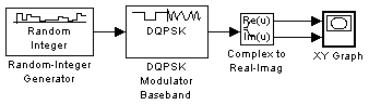
DQPSK Signal Constellation Points and Transitions
The model below plots the output of the DQPSK Modulator Baseband block. The image shows the possible transitions from each symbol in the DQPSK signal constellation to the next symbol.
To open the completed model, click here in the MATLAB Help browser. To build the model, gather and configure these blocks:
4.
randseed function.
.01.
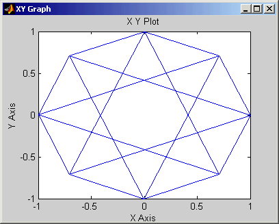
Use the blocks' default parameters unless otherwise instructed. Connect the blocks as in the figure. Running the model produces the following plot. The plot reflects the transitions among the eight DQPSK constellation points.
This plot illustrates  /4-DQPSK modulation, because the default Phase offset parameter in the DQPSK Modulator Baseband block is
 pi/4. To see how the phase offset influences the signal constellation, change the Phase offset parameter in the DQPSK Modulator Baseband block to pi/8 or another value. Run the model again and observe how the plot changes.
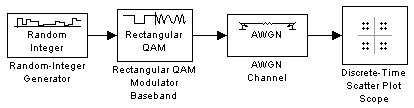
Rectangular QAM Modulation and Scatter Diagram
The model below uses the M-QAM Modulator Baseband block to modulate random data. After passing the symbols through a noisy channel, the model produces a scatter diagram of the noisy data. The diagram suggests what the underlying signal constellation looks like and shows that the noise distorts the modulated signal from the constellation.
To open the completed model, click here in the MATLAB Help browser. To build the model, gather and configure these blocks:
16
randseed function
.1
20
.1
160
80
figposition([2.5 55 35 35]);
QAM Scatter Plot
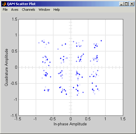
Connect the blocks as in the figure. Also, from the model window's Simulation menu, choose Simulation parameters; then, in the Simulation Parameters dialog box, set Stop time to 250. Running the model produces a scatter diagram like the following one. Your plot might look somewhat different, depending on your Initial seed value in the Random Integer Generator block. Because the modulation technique is 16-QAM, the plot shows 16 clusters of points. If there were no noise, the plot would show the 16 exact constellation points instead of clusters around the constellation points.
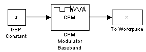
Phase Tree for Continuous Phase Modulation
This example plots a phase tree associated with a continuous phase modulation scheme. A phase tree is a diagram that superimposes many curves, each of which plots the phase of a modulated signal over time. The distinct curves result from different inputs to the modulator.
This example uses the CPM Modulator Baseband block for its numerical computations. The block is configured so that it uses a raised cosine filter pulse shape. The example also illustrates how you can use Simulink and MATLAB together. The example uses MATLAB commands to run a series of simulations with different input signals, to collect the simulation results, and to plot the full data set.
The first step of this example is to build the model. To open the completed model, click here in the MATLAB Help browser. To build the model, gather and configure these blocks:
s (which will be in the MATLAB workspace)
1
2.
2/3.
2.
x.
Do not run the model, because the variable s is not yet defined in the MATLAB workspace. Instead, save the model to a directory on your MATLAB path, using the filename doc_phasetree.
The second step of this example is to execute these commands in MATLAB.
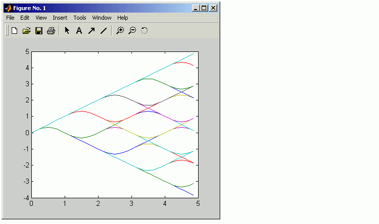
% Parameters from the CPM Modulator Baseband block
M_ary_number = 2;
modulation_index = 2/3;
pulse_length = 2;
samples_per_symbol = 8;
opts = simset('SrcWorkspace','Current',...
   'DstWorkspace','Current');

L = 5;  % Symbols to display
pmat = [];
for ip_sig = 0:(M_ary_number^L)-1
    s = de2bi(ip_sig,L,M_ary_number,'left-msb');
    % Apply the mapping of the input symbol to the CPM
    % symbol 0 -> -(M-1), 1 -> -(M-2), etc.
    s = 2*s'+1-M_ary_number;
    sim('doc_phasetree', .9, opts); % Run model to generate x.
    pmat(:,ip_sig+1) = unwrap(angle(x(:))); % Next column of pmat
end;
pmat = pmat/(pi*modulation_index);
t = (0:L*samples_per_symbol-1)'/samples_per_symbol;
plot(t,pmat); figure(gcf); % Plot phase tree.
The resulting plot follows. Each curve represents a different instance of simulating the CPM Modulator Baseband block with a distinct (constant) input signal.
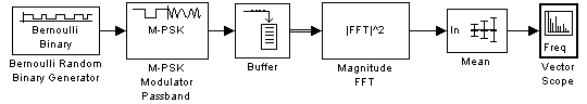
The example below uses passband phase shift keying modulation and displays the spectrum of the modulated signal. The M-PSK Modulator Passband block's parameters satisfy necessary requirements for passband simulation because
These requirements are mentioned on the reference page for the M-PSK Modulator Passband block.
To open the completed model, click here in the MATLAB Help browser. To build the model, gather and configure these blocks:
[.5, .5].
randseed function.
.1.
4.
.1.
1000.
pi/4.
1/3000.
1024.
100.
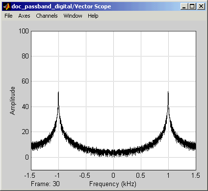
Connect the blocks as in the preceding figure. Also, from the model window's Simulation menu, choose Simulation parameters; then in the Simulation Parameters dialog box, set Stop time to 10. Running the model produces the following spectral plot.
You might want to vary the modulation technique to see how this plot would change. For example, you can try replacing the M-PSK Modulator Passband block with the M-DPSK Modulator Passband or OQPSK Modulator Passband block.
| | Upsampled Signals and Rate Changes | Selected Bibliography for Digital Modulation | |