| Communications Blockset |
  |
AWGN Channel
Add white Gaussian noise to the input signal
Library
Channels
Description

The AWGN Channel block adds white Gaussian noise to a real or complex input signal. When the input signal is real, this block adds real Gaussian noise and produces a real output signal. When the input signal is complex, this block adds complex Gaussian noise and produces a complex output signal. This block inherits its sample time from the input signal.
This block uses the DSP Blockset's Random Source block to generate the noise. The Initial seed parameter in this block initializes the noise generator. Initial seed can be either a scalar or a vector whose length matches the number of channels in the input signal. For details on Initial seed, see the Random Source block reference page in the DSP Blockset User's Guide.
Frame-Based Processing and Input Dimensions
This block can process multichannel signals that are frame-based or sample-based. The guidelines below indicate how the block interprets your data, depending on the data's shape and frame status:
- If your input is a sample-based scalar, then the block adds scalar Gaussian noise to your signal.
- If your input is a sample-based vector or a frame-based row vector, then the block adds independent Gaussian noise to each channel.
- If your input is a frame-based column vector, then the block adds a frame of Gaussian noise to your single-channel signal.
- If your input is a frame-based m-by-n matrix, then the block adds a length-m frame of Gaussian noise independently to each of the n channels.
The input cannot be a sample-based m-by-n matrix if both m and n are greater than 1.
Specifying the Variance Directly or Indirectly
You can specify the variance of the noise generated by the AWGN Channel block using one of four modes:
- Signal to noise ratio (Es/No), where the block calculates the variance from these quantities that you specify in the block mask:
- Es/No, the ratio of signal energy to noise power spectral density
- Input signal power, the power of the input symbols
- Symbol period
- Signal to noise ratio (SNR), where the block calculates the variance from these quantities that you specify in the block mask:
- SNR, the ratio of signal power to noise power
- Input signal power, the power of the input samples
- Variance from mask, where you specify the variance in the block mask. The value must be positive.
- Variance from port, where you provide the variance as an input to the block. The variance input must be positive, and its sampling rate must equal that of the input signal. If the first input signal is sample-based, then the variance input must be sample-based. If the first input signal is frame-based, then the variance input can be either frame-based with exactly one row, or sample-based.
In both Variance from mask mode and Variance from port mode, these rules describe how the block interprets the variance:
- If the variance is a scalar, then all signal channels are uncorrelated but share the same variance.
- If the variance is a vector whose length is the number of channels in the input signal, then each element represents the variance of the corresponding signal channel.
| Note
If you apply complex input signals to the AWGN Channel block, then it adds complex zero-mean Gaussian noise with the calculated or specified variance. The variance of each of the quadrature components of the complex noise is half of the calculated or specified value.
|
Relationship Between Es/No and SNR Modes
For complex input signals, the AWGN Channel block relates Es/N0 and SNR according to the following equation:
where
- Es = Signal energy (Joules)
- N0 = Noise power spectral density (Watts/Hz)
- Tsym is the Symbol period of the block in Es/No mode (s)
- Tsamp is the inherited Sample time of the block (s)
You can derive this relationship as follows:

where
- S = Input signal power (watts)
- N = Noise power (Watts)
- Bn = Noise bandwidth (Hz)
- Fs = Sampling frequency (Hz)
Note that  . The quantity Es/N0 is the signal-to-noise ratio with the noise measured in a symbol rate bandwidth. The quantity S/N is measured in a sample rate bandwidth.
For real signal inputs, the AWGN Channel block relates Es/N0 and SNR according to the following equation:
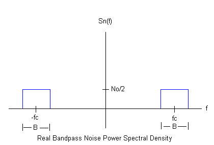
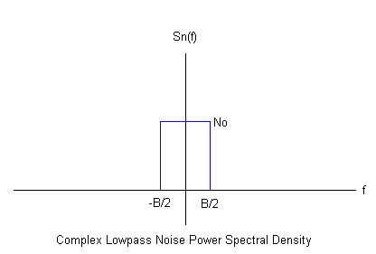
Note that the equation for the real case differs from the corresponding equation for the complex case by a factor of 2. This is so because the block uses a noise power spectral density of N0/2 Watts/Hz for real input signals, versus N0 Watts/Hz for complex signals.
The following figures illustrate the difference between the real and complex cases by showing the noise power spectral densities Sn(f) of a real bandpass white noise process and its complex lowpass equivalent.


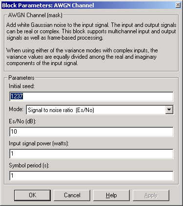
Dialog Box

- Initial seed
- The seed for the Gaussian noise generator.
- Mode
- The mode by which you specify the noise variance: Signal to noise ratio (Es/No), Signal to noise ratio (SNR), Variance from mask, or Variance from port.
- Es/No (dB)
- The ratio of signal energy per symbol to noise power spectral density, in decibels. This field appears only if Mode is set to Es/No.
- SNR (dB)
- The ratio of signal power to noise power, in decibels. This field appears only if Mode is set to SNR.
- Input signal power (watts)
- The root mean square power of the input symbols (if Mode is Es/No) or input samples (if Mode is SNR), in watts. This field appears only if Mode is set to either Es/No or SNR.
- Symbol period (s)
- The duration of a channel symbol, in seconds. This field appears only if Mode is set to Es/No.
- Variance
- The variance of the white Gaussian noise. This field appears only if Mode is set to Variance from mask.
See Also
Random Source (DSP Blockset)
Reference
[1] Proakis, John G., Digital Communications, 4th Ed., McGraw-Hill, 2001.
 | APP Decoder | | Barker Code Generator |  |


 . The quantity Es/N0 is the signal-to-noise ratio with the noise measured in a symbol rate bandwidth. The quantity S/N is measured in a sample rate bandwidth.
