| DSP Blockset | |
Buffer the input sequence to a smaller or larger frame size.
Library
Signal Management / Buffers
Description
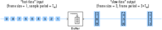
The Buffer block redistributes the input samples to a new frame size, larger or smaller than the input frame size. Buffering to a larger frame size yields an output with a slower frame rate than the input, as illustrated below for scalar input.
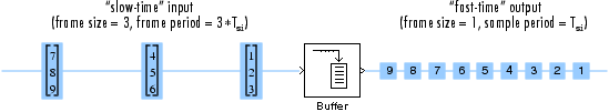
Buffering to a smaller frame size yields an output with a faster frame rate than the input, as illustrated below for scalar output.
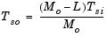
The block coordinates the output frame size and frame rate of nonoverlapping buffers so that the sample period of the signal is the same at both the input and output, Tso = Tsi.
Sample-Based Operation
Sample-based inputs are interpreted by the Buffer block as independent channels of data. Thus, a sample-based length-N vector input is interpreted as N independent samples.
In sample-based operation, the Buffer block creates frame-based outputs from sample-based inputs. A sequence of sample-based length-N vector inputs (1-D, 2-D row, or 2-D column) is buffered into an Mo-by-N matrix, where Mo is specified by the Output buffer size parameter (Mo>1). That is, each input vector becomes a row in the N-channel frame-based output matrix. When Mo=1, the input is simply passed through to the output, and retains the same dimension.
Sample-based full-dimension matrix inputs are not accepted.
The Buffer overlap parameter, L, specifies the number of samples (rows) from the current output to repeat in the next output, where L < Mo. For 0  L < Mo, the number of new input samples that the block acquires before propagating the buffered data to the output is the difference between the Output buffer size and Buffer overlap, Mo-L.
The output frame period is (Mo-L)*Tsi, which is equal to the input sequence sample period, Tsi, when the Buffer overlap is Mo-1. For L < 0, the block simply discards L input samples after the buffer fills, and outputs the buffer with period (Mo-L)*Tsi, which is longer than the zero-overlap case.
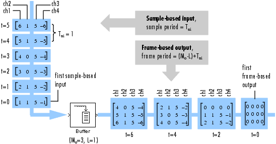
In the model below, the block buffers a four-channel sample-based input using a Output buffer size of 3 and a Buffer overlap of 1.
Note that the input vectors do not begin appearing at the output until the second row of the second matrix. This is due to the block's latency (see Latency below). The first output matrix (all zeros in this example) reflects the block's Initial conditions setting, while the first row of zeros in the second output is a result of the one-sample overlap between consecutive output frames.
You can use the rebuffer_delay function with a frame size of 1 to precisely compute the delay (in samples) for sample-based signals. For the above example,
This agrees with the four samples of delay (zeros) per channel shown in the figure above.
Frame-Based Operation
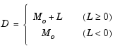
In frame-based operation, the Buffer block redistributes the samples in the input frame to an output frame with a new size and rate. A sequence of Mi-by-N matrix inputs is buffered into a sequence of Mo-by-N frame-based matrix outputs, where Mo is the output frame size specified by the Output buffer size parameter (i.e., the number of consecutive samples from the input frame to buffer into the output frame). Mo can be greater or less than the input frame size, Mi. Each of the N input channels is buffered independently.
The Buffer overlap parameter, L, specifies the number of samples (rows) from the current output to repeat in the next output, where L < Mo. For 0 L < Mo, the number of new input samples the block acquires before propagating the buffered data to the output is the difference between the Output buffer size and Buffer overlap, Mo-L.
The input frame period is Mi*Tsi, where Tsi is the sample period. The output frame period is (Mo-L)*Tsi, which is equal to the sequence sample period when the Buffer overlap is Mo-1. The output sample period is therefore related to the input sample period by
Negative Buffer overlap values are not permitted.
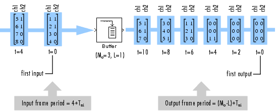
In the model below, the block buffers a two-channel frame-based input using a Output buffer size of 3 and a Buffer overlap of 1.
Note that the sequence is delayed by eight samples, which is the latency of the block in the Simulink multitasking mode for the parameter settings of this example (see Latency below). The first eight output samples therefore adopt the value specified for the Initial conditions, which is assumed here to be zero. Use the rebuffer_delay function to determine the block's latency for any combination of frame size and overlap.
Zero Latency
In the Simulink single tasking mode, the Buffer block has zero tasking latency (the first input sample, received at t=0, appears as the first output sample) for the following special cases:
0)
Nonzero Latency
Sample-Based Operation. For all cases of sample-based single-tasking operation other than those listed above, the Buffer block's buffer is initialized to the value(s) specified by the Initial conditions parameter, and the block reads from this buffer to generate the first D output samples, where
If the Buffer overlap, L, is zero, the Initial conditions parameter can be a scalar to be repeated across the first Mo output samples, or a length-Mo vector containing the values of the first Mo output samples. For nonzero Buffer overlap, the Initial conditions parameter must be a scalar.
Frame-Based Operation. For frame-based single-tasking operation and all multitasking operation, use the rebuffer_delay function to compute the exact delay (in samples) that the Buffer block introduces for a given combination of buffer size and buffer overlap.
For general buffering between arbitrary frame sizes, the Initial conditions parameter must be a scalar value, which is then repeated across all elements of the initial output(s). However, in the special case where the input is 1-by-N (and the block's output is therefore an Mo-by-N matrix), Initial conditions can be:
In the special case where the output is 1-by-N (the result of unbuffering an Mi-by-N frame-based matrix), Initial conditions can be:
See Excess Algorithmic Delay (Tasking Latency) and "The Simulation Parameters Dialog Box" in the Simulink documentation for more information about block rates and the Simulink tasking modes.
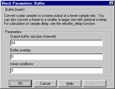
Dialog Box
Supported Data Types
To learn how to convert to the above data types in MATLAB and Simulink, see Supported Data Types and How to Convert to Them.
See Also
| Delay Line |
DSP Blockset |
| Unbuffer |
DSP Blockset |
rebuffer_delay |
DSP Blockset |
See Buffering Sample-Based and Frame-Based Signals for related information. Also see Buffers for a list of all the blocks in the Buffers library.
| | Backward Substitution | Burg AR Estimator | |