The Wehrsen Machine
Introduction
 In
1907 [p77], Heinrich Wommelsdorf
described an electrostatic machine that was a variation of the Holtz machine of the first kind, but with a
rotating disk made of ebonite having embedded sectors accessed
through buttons at the disk surface, and inductor plates embedded
in celluloid attached to a fixed ebonite disk. Machines with this
structure were popularized by the instrument builder Alfred
Wehrsen, in Berlin, that also patented this form of disk in 1903
[DE154175], and
so it is sometimes mentioned as the "Wehrsen machine" [1] (see note in [p80]),
I find this name convenient to separate this machine from the
"Condenser machine", that
is more associated with Wommelsdorf's work and is quite
different, and so will call the machine here by this name.
In
1907 [p77], Heinrich Wommelsdorf
described an electrostatic machine that was a variation of the Holtz machine of the first kind, but with a
rotating disk made of ebonite having embedded sectors accessed
through buttons at the disk surface, and inductor plates embedded
in celluloid attached to a fixed ebonite disk. Machines with this
structure were popularized by the instrument builder Alfred
Wehrsen, in Berlin, that also patented this form of disk in 1903
[DE154175], and
so it is sometimes mentioned as the "Wehrsen machine" [1] (see note in [p80]),
I find this name convenient to separate this machine from the
"Condenser machine", that
is more associated with Wommelsdorf's work and is quite
different, and so will call the machine here by this name.
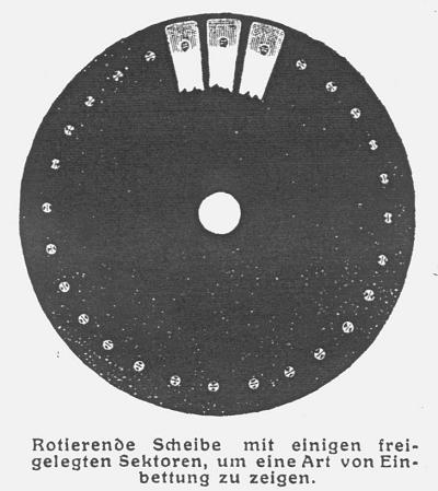
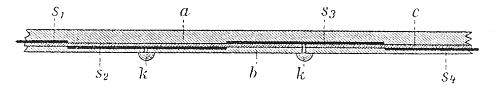
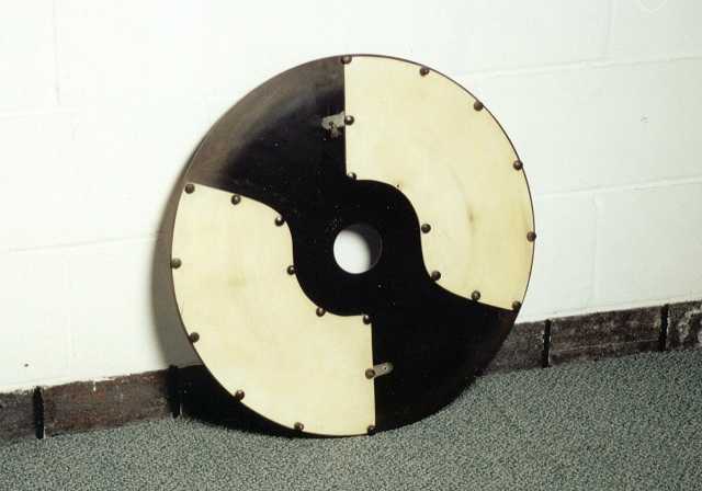
The machine described in 1907 had a rotating
disk made of three or four layers of ebonite vulcanized
together, with sets of intercalated sectors
distributed through them, in two or three planes separated by
thin ebonite disks, for high insulation. The idea was described
in a patent by Wommelsdorf issued in
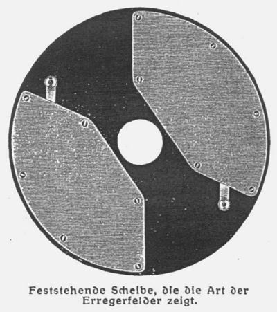
1908. The fixed disk was a bit larger,
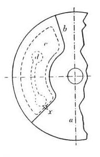
and had inductor plates made of paper
with a central metal strip, embedded in celluloid. As celluloid
is a flexible material, the inductor assemblies were mounted with
screws in a rigid ebonite disk. The inductors had exposed brushes
or points at one side, used to take charge from the bare back
side of the rotating disk at a small angle before the charge
collectors, as in a Holtz machine of the first kind. At the front
side of the rotating disk, there were charge collectors with
adjustable brushes connected to the output terminals and Leyden
jars through switches, an adjustable neutralizing bar with
brushes, and switches that could connect the inductor plates
directly to the charge collectors for easier startup as a Belli
machine.
The machine could be motorized, and could run at high speeds,
producing a relatively high current due to the efficient use of
the rotating disk area by the embedded sectors, and high voltage
due to the good insulation.
Versions of the machine were built at least until the 1920's,
in several models and sizes, with one or two rotating disks, but
almost always with the characteristic appearance given by the
white celluloid inductor plates and the buttons in the rotating
disks.
Some examples:
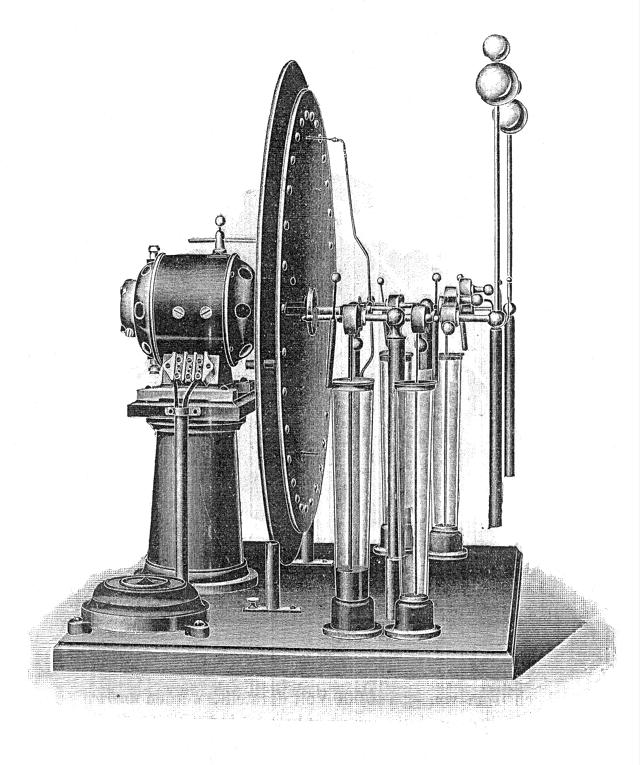
 An early
machine [p77], with switchable
sets of Leyden jars, direct motor drive, and no apparent
celluloid plates.
An early
machine [p77], with switchable
sets of Leyden jars, direct motor drive, and no apparent
celluloid plates.
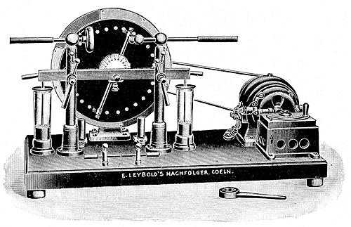
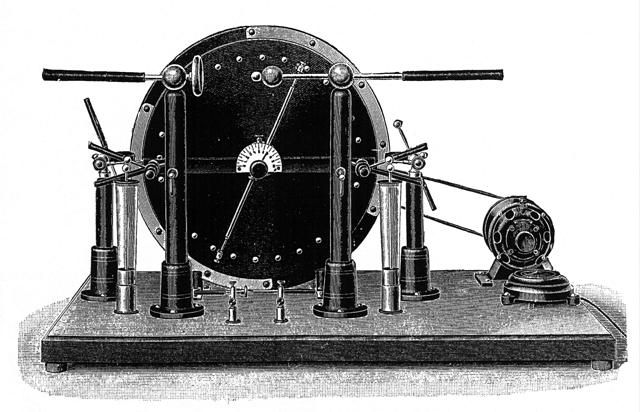
Another machine with direct motor drive
[26], but with celluloid plates and startup switches connecting
the charge collectors to the inductors or to the output.
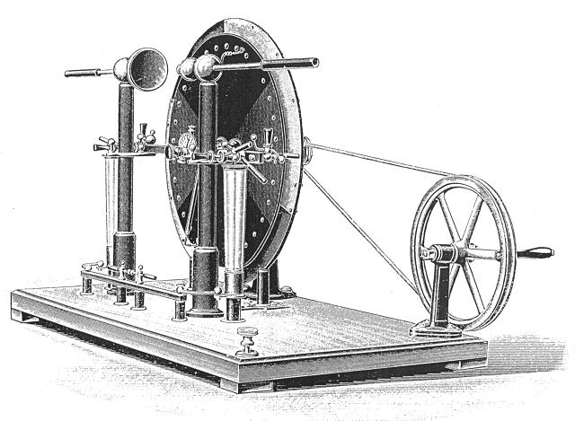
A small machine [22], without visible
startup switches.
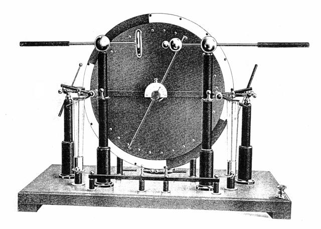
A machine with segmented Leyden jars
[22], switches only for the Leyden jars, and the neutralizer in a
strange position.
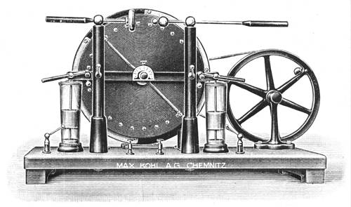
A machine with vertical output switches
[22] and motor drive.
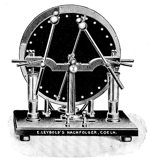
A machine with two rotating disks [1],
motor drive, and a complete set of switches, mentioned as the
"Wehrsen machine".
A nice big machine [22] with segmented
Leyden jars and no startup switches.
Wehrsen's "Mercedes" machine
[34], with many switches. A version with 2
rotating disks [34], also with a complete set of switches and
Leyden jars insulated from the machine's base.
A machine with two rotating disks,
dated
from 1911 that exists at the Cavendish Institute, in England.
Detail of the switches (possibly
incorrectly assembled, as there is no way to connect the charge
collectors to the output terminals in this way). Back view, showing the back neutralizer and the
startup switches. The fixed disk,
showing the celluloid inductor plates. Another view
showing the switches, and another, from the
other side.
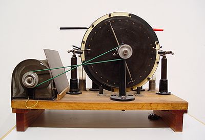
A similar machine, but with an electric motor, exists at the Technical
University
of Clausthal, Germany. Left view. Right view. Pictures sent by Prof. Friedrich
Balck.
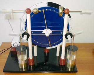
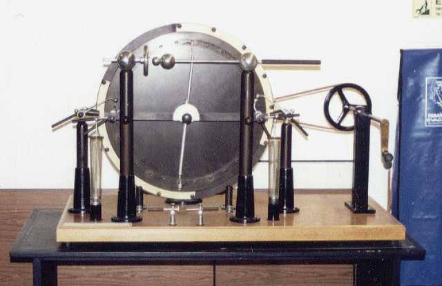
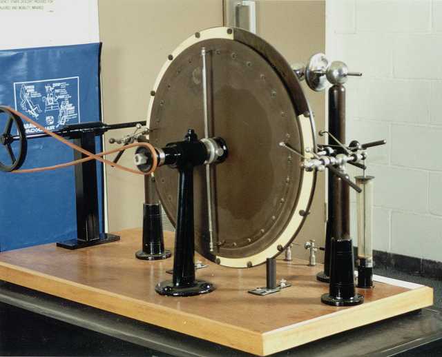
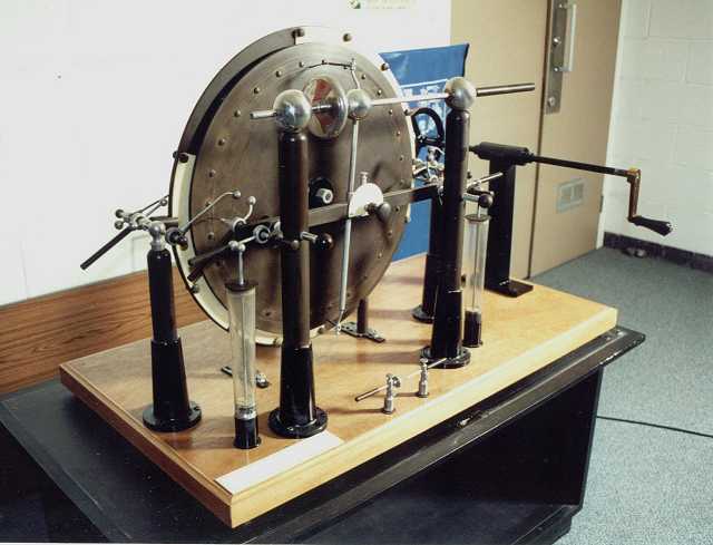
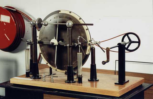
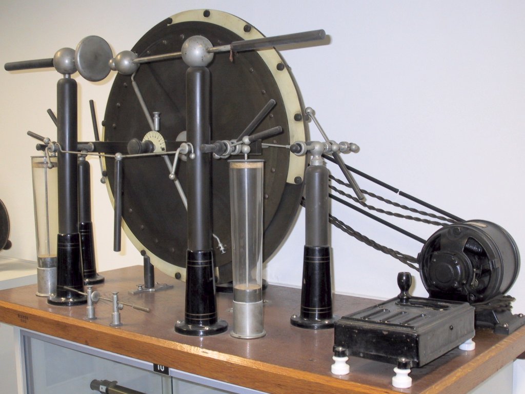
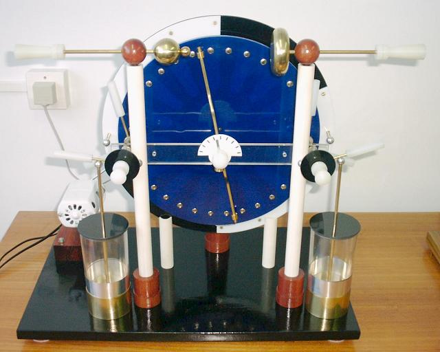
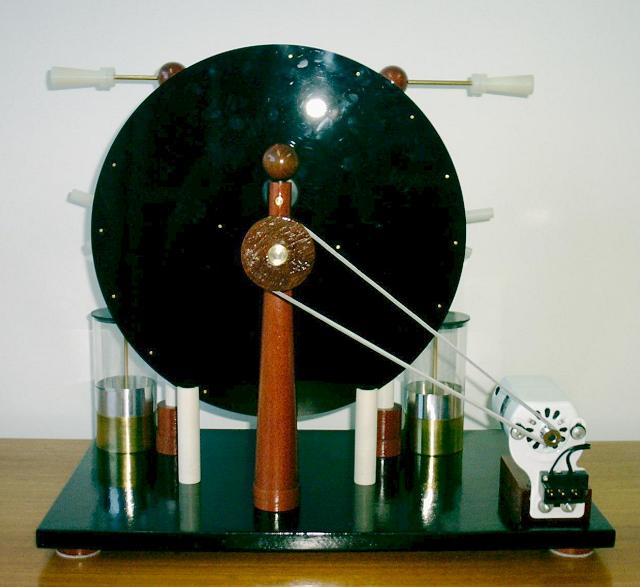
A still functional machine is used in demonstrations
at the Bonn University, Germany. It's the machine on the picture above.
Side view. Back view. Photos sent
by Michael Kortmann. He sent also this catalog from the Alfred Wehrsen company.
A model of the Wehrsen machine
 By August 2001, I started to build a large Wehrsen machine, with a 60 cm fixed
disk and 55 cm rotating disk with two layers of intercalated
internal sectors. However, I become worried about the methods to
use to construct the disks and several other details of the
machine, and decided to make first a smaller machine to
experiment with adequate techniques and see how this kind of
machine works.
By August 2001, I started to build a large Wehrsen machine, with a 60 cm fixed
disk and 55 cm rotating disk with two layers of intercalated
internal sectors. However, I become worried about the methods to
use to construct the disks and several other details of the
machine, and decided to make first a smaller machine to
experiment with adequate techniques and see how this kind of
machine works.
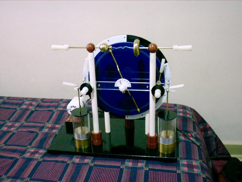
I started by the disk, that is composed by 3 blue acrylic
plates with 2.5 mm of thickness and 30 cm of diameter, with 32
sectors in two layers of 16 separated by the central disk. The
sectors are as the sectors of a Wimshurst
machine, dimensioned to look exactly side by side when seen
through the disk, with 7.5 cm of length, at 5 mm of the border of
the disk The frontal disk has 32 holes for access to the sectors,
aligned with 16 holes in the central disk for access to the
sectors in the second layer. After the holes were made and the
sectors, made of adhesive aluminum foil, were applied, the three
disks were glued together with hot glue. The glue was spread with
the regular application pistol in continuous beads around the
sectors, connection holes, outer edge and inner edge of the
sectored area, and the disks were then heated in an oven between
glass plates, pressed by weights. I inserted some metal blocks
for aligning the holes, at the center and three of the holes
crossing two disks (the blocks had threads tapped on them, so
they could be easily pulled out with a screw if becoming glued).
I heated the disk to 200 degrees for about 20 minutes, until I
noticed that the glue had melted completely, and all the moisture
of the assembly had disappeared. I then let the assembly cool in
the oven, and removed the excess of glue from the holes and
edges. The result could be better if I had inserted aligning
blocks in all the holes crossing two disks, and had used less
heating. It would be probably enough to let the oven on until all
the moisture disappears and the acrylic starts to soften and
adhere to the glass (easily visible through the glass) and then
turn it off and let the heat spread through the assembly while it
cools. The disks deformed a bit, and some of the holes got
somewhat misaligned. The glass plates kept the surfaces flat,
although some irregularities appeared, specially in the upper
disk. I could, however, trim the edge of the assembled disk and
polish it, with a good result. The 32 buttons were made of rivet
heads glued with cyanoacrylate glue to the holes, with small
springs inside to ensure good contact with the sectors. I tested
all the sector pairs for insulation, trying to force a spark
between the sectors. I had to repair two points with more glue
through the holes, and one defect in the back sector group could
not be repaired. These defects could be prevented with more
attention while spreading the glue. In other points, the
insulation was perfect.
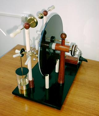 The fixed disk is made in black acrylic,
2.5 mm thick. It has a hole at the center for the boss that holds
the rotating disk, and two white acrylic spark shields fixed by
small brass screws, with the inductor plates mounted on their
under sides. The inductor plates are made in paper, with a strip
of aluminum foil at the center, with lateral connections to the
switches that make contact with the charge collectors, and
brushes of thin metal foil strips (silver) to collect charges
from the back side of the rotating disk. The inductors are
insulated by two layers of adhesive plastic foil, that cover the
entire back surfaces of the spark shields. In this way, the
inductors are completely encased in solid insulators. The layers
of adhesive plastic foil are essential. Without them charges leak
abundantly through the internal edges of the plates, opposite to
where the brushes are mounted, and the machine doesn't produce
high voltages.
The fixed disk is made in black acrylic,
2.5 mm thick. It has a hole at the center for the boss that holds
the rotating disk, and two white acrylic spark shields fixed by
small brass screws, with the inductor plates mounted on their
under sides. The inductor plates are made in paper, with a strip
of aluminum foil at the center, with lateral connections to the
switches that make contact with the charge collectors, and
brushes of thin metal foil strips (silver) to collect charges
from the back side of the rotating disk. The inductors are
insulated by two layers of adhesive plastic foil, that cover the
entire back surfaces of the spark shields. In this way, the
inductors are completely encased in solid insulators. The layers
of adhesive plastic foil are essential. Without them charges leak
abundantly through the internal edges of the plates, opposite to
where the brushes are mounted, and the machine doesn't produce
high voltages.
I made a light base board in plywood, leveled, polished, and
painted in black. The rotating disk is supported by a single
support turned in hard wood, that has a conical upright part and
a horizontal cylinder at the top. The cylinder is crossed by a 6
mm steel axle, running on teflon bearings, that has at the front
side a nylon boss that supports the rotating disk, fixed by three
screws through a compressible plastic washer, and at the back
side a pulley. Above the same support, there is an adjustable
brass bar crossing a wood cylinder, that supports the fixed disk,
holding it through a screw mounted in a nylon block glued to the
disk. The bar can be removed by unscrewing it for disassembly of
the machine. A wood ball with a threaded rod fixes the bar to the
support structure. The fixed disk is supported below by two
sections of PVC tube, with slots for the disk and internal wood
cilynders at the lower ends for fixation, that can be mounted at
adjustable depth (they are mounted over slots in the base),
completing the system that allows adjustment of the distance
between the fixed and rotating disks. The two terminal supports
at the front of the machine are PVC tubes inserted in wood bases.
Also mounted in the base are the Leyden jars and the motor. All
the parts are fixed to the base through 3/16" threaded rods,
with washers and nuts below.
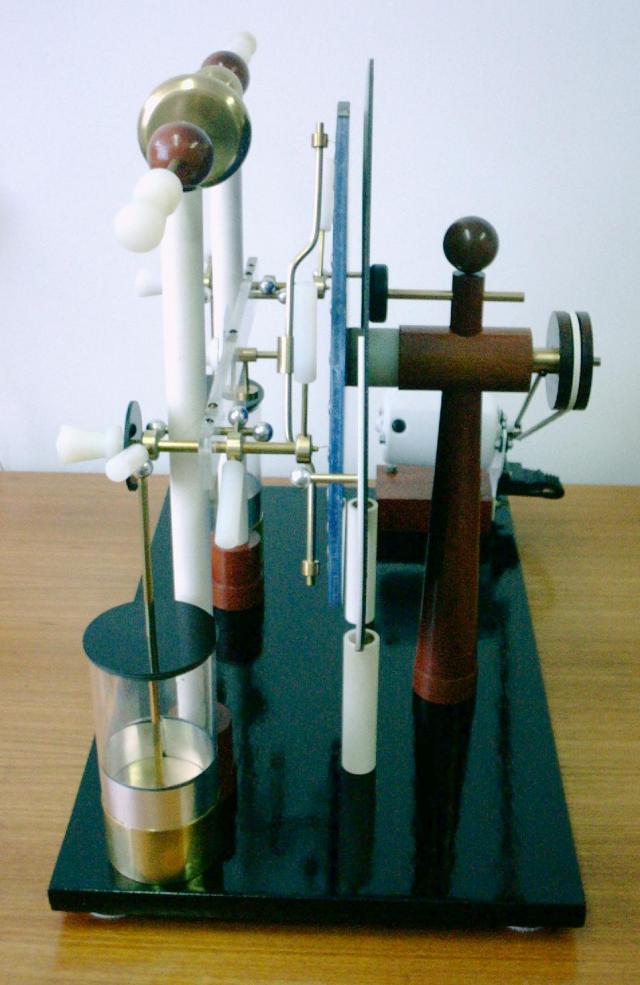
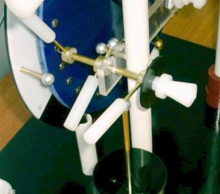 The charge collector and terminal
assemblies are quite complicated. A transparent acrylic bar fixed
to the two vertical supports holds at its extremities, aligned
with the buttons in the rotating disk, two 1/4" brass tubes
(drilled rods). These tubes are crossed lengthwise by 1/8"
brass rods, held by light friction, that hold the charge
collecting brushes at the back end and insulating handles at the
front end. This allows the brushes to be pulled out for distance
adjustment and maintenance. Over the tubes are mounted three
switches, that allow contacts between the inductor plates and the
charge collectors, the charge collectors and the spark terminals,
and the charge collectors and the Leyden jars. The switches turn
around brass rings with cores of nylon. Inside the nylon cores
there are holes with small springs to keep the switches in place
and ensure good contact between the rings and the tubes. The
switches have insulating handles made in nylon, and contacts with
aluminum balls. At the center of the horizontal bar, there is a
neutralizer bar, with brushes at the ends touching the buttons on
the rotating disk, and a button with a dial that allows precise
positioning, rotation, and distance adjustment of the
neutralizer. A thumb screw allows the fixation of the
neutralizer. The horizontal bar is fixed to the upright supports
by short 3/16" brass bars crossing the assembly, terminated
in aluminum balls. Inside the PVC tubes, they support vertical
bars that make contact with the terminals above, centered in the
tubes by small wood cylinders that they cross, at the two
extremities. The terminals slide on wood balls mounted over these
rods, pressed inside the wood balls by steel balls mounted over
springs that insert in holes in the bars inside the tubes. The
terminals are of the double ball-plane type, made by metal
spinning, and have handles turned in nylon. All the parts are
fixed together by screws or glue.
The charge collector and terminal
assemblies are quite complicated. A transparent acrylic bar fixed
to the two vertical supports holds at its extremities, aligned
with the buttons in the rotating disk, two 1/4" brass tubes
(drilled rods). These tubes are crossed lengthwise by 1/8"
brass rods, held by light friction, that hold the charge
collecting brushes at the back end and insulating handles at the
front end. This allows the brushes to be pulled out for distance
adjustment and maintenance. Over the tubes are mounted three
switches, that allow contacts between the inductor plates and the
charge collectors, the charge collectors and the spark terminals,
and the charge collectors and the Leyden jars. The switches turn
around brass rings with cores of nylon. Inside the nylon cores
there are holes with small springs to keep the switches in place
and ensure good contact between the rings and the tubes. The
switches have insulating handles made in nylon, and contacts with
aluminum balls. At the center of the horizontal bar, there is a
neutralizer bar, with brushes at the ends touching the buttons on
the rotating disk, and a button with a dial that allows precise
positioning, rotation, and distance adjustment of the
neutralizer. A thumb screw allows the fixation of the
neutralizer. The horizontal bar is fixed to the upright supports
by short 3/16" brass bars crossing the assembly, terminated
in aluminum balls. Inside the PVC tubes, they support vertical
bars that make contact with the terminals above, centered in the
tubes by small wood cylinders that they cross, at the two
extremities. The terminals slide on wood balls mounted over these
rods, pressed inside the wood balls by steel balls mounted over
springs that insert in holes in the bars inside the tubes. The
terminals are of the double ball-plane type, made by metal
spinning, and have handles turned in nylon. All the parts are
fixed together by screws or glue.
The charge collector and neutralizer brushes were made from
brushes taken from the output slot of a discarded laser printer.
The brushes that charge the inductor plates were made with thin
silver strips. These materials proved to be the most adequate so
far, not breaking easily and causing reliable startup of the
machine. The Leyden jars were made from tall acrylic drinking
glasses, mounted on cups made of soldered brass plates,
interconnected by a wire under the base. Their capacitance is of
57 pF.
The machine is powered by a sewing machine motor, with a pedal
for speed control. The motor is fixed to a wood block at a corner
of the base by its normal fixation structure, and powers the
machine through a polyurethane cord. The maximum listed maximum
speed of the motor is 7000 rpm, what is enough to turn the disk
at 21 turns per second through the 1:5.5 diameter ratio of the
pulleys.
Operation:
 The machine self-starts easily. In
conditions of high humidity, or after a long time without
operation, it is necessary to close the switches that connect the
inductors to the charge collectors. After the startup it works
better with the switches open, or each spark discharges the
inductors. The ball-plane gap only produces long
sparks with the balls being at the positive side. If the
polarity is inverted (a characteristic hissing noise can be heard
in this case), it can be reversed by moving the neutralizer
beyond the spark shields for a moment and then returning it.
Actually, any sudden movement of the neutralizer causes a
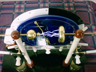
reversal when the gap is widely open. The machine produces more
current when the neutralizer is at low angle, but longer sparks
without polarity reversals only when the neutralizer is at high
angle. For reliable operation, the distance between the disks
must be quite high, 9 mm. With shorter distances the spark length
is smaller and frequent polarity reversals are a problem. The
output current is not significantly affected by the distance. It
reaches 70 µA with the motor at full speed (measured from one
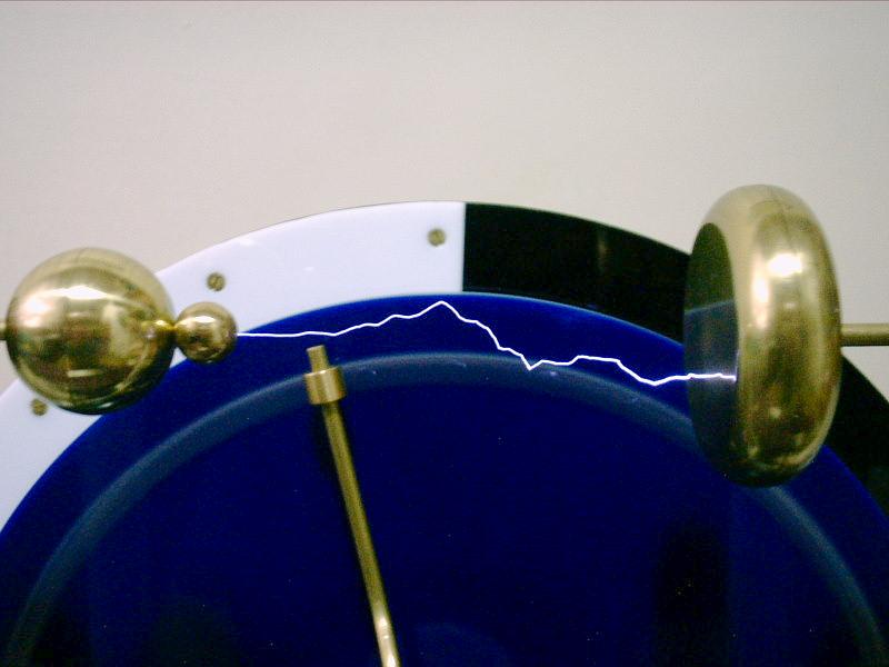
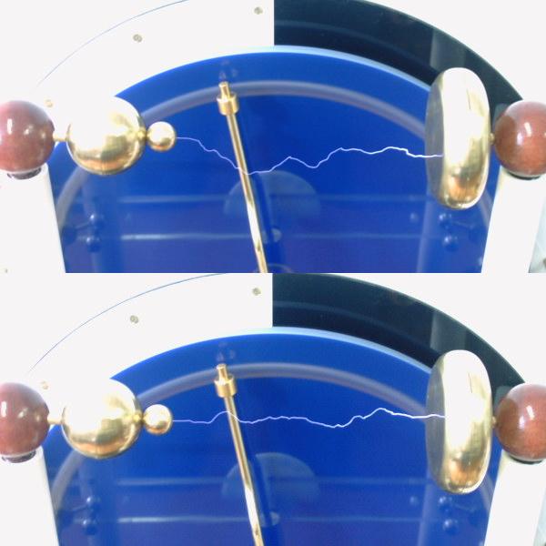
terminal to the neutralizer bar). The maximum spark length
observed was 12.5 cm, that is the maximum distance allowed by the
terminal assembly. At this distance, however, there is
significant leakage between the terminals and the neutralizer and
disks, and sparks occur only in dry air. Consistent output is
obtained up to 11 cm sparks. With the
neutralizer at high angle, it keeps the same polarity for
indefinite time if the neutralizer is not moved and the speed is
not reduced. Humidity appears to have little effect on the
machine, at least much less than in an open machine. It also
produces little ozone, as there is almost no sparking on its
structure.
The machine self-starts easily. In
conditions of high humidity, or after a long time without
operation, it is necessary to close the switches that connect the
inductors to the charge collectors. After the startup it works
better with the switches open, or each spark discharges the
inductors. The ball-plane gap only produces long
sparks with the balls being at the positive side. If the
polarity is inverted (a characteristic hissing noise can be heard
in this case), it can be reversed by moving the neutralizer
beyond the spark shields for a moment and then returning it.
Actually, any sudden movement of the neutralizer causes a
reversal when the gap is widely open. The machine produces more
current when the neutralizer is at low angle, but longer sparks
without polarity reversals only when the neutralizer is at high
angle. For reliable operation, the distance between the disks
must be quite high, 9 mm. With shorter distances the spark length
is smaller and frequent polarity reversals are a problem. The
output current is not significantly affected by the distance. It
reaches 70 µA with the motor at full speed (measured from one
terminal to the neutralizer bar). The maximum spark length
observed was 12.5 cm, that is the maximum distance allowed by the
terminal assembly. At this distance, however, there is
significant leakage between the terminals and the neutralizer and
disks, and sparks occur only in dry air. Consistent output is
obtained up to 11 cm sparks. With the
neutralizer at high angle, it keeps the same polarity for
indefinite time if the neutralizer is not moved and the speed is
not reduced. Humidity appears to have little effect on the
machine, at least much less than in an open machine. It also
produces little ozone, as there is almost no sparking on its
structure.
The switches that connect the charge collectors to the
terminals have little utility. They increase the spark length
when the machine is with reverse polarity (negative at the ball
terminal) when open and reduce a bit the occurrence of
"failed sparks" when the terminals are at large
distance if slightly open, but their main utility appears to be
to allow touching of the terminals while the machine is still
running without shocks, but the neutralizer can be used for this,
short-circuiting the charge collectors when almost horizontal.
The switches for the Leyden jars serve to disconnect them. The
terminals produce a nice display in the dark when the jars are
disconnected, with a thick plume of corona flowing from the
positive ball terminal to the plane terminal.
The spark length and current observed are consistent with what
can be expected for this machine. The
current is quite high, but I don't have yet a good measurement of
the relation between current and disk speed. The ball-plane gap
doesn't require much voltage to generate long sparks, and so the
actual voltage generated by the machine may be not so high. More
measurements will eventually be added here.
Conclusions:
The machine works well and reliably, with impressive output.
The motorized operation and the ball-plane terminals, however,
turns difficult a clear comparison with my other machines of
similar size. It doesn't look better than a double
Voss machine, that is self-starting without switching, and
reaches almost the same output with manual operation. The machine
would work well with manual cranking too, as it's very easy to
turn. Its output current is theoretically similar to what can be
obtained with a sectorless machine (as a Bonetti
machine) with one or two rotating disks, turning at the same
speed, but the output voltage of a Bonetti machine is higher. It
is certainly better than a Holtz machine,
that has a similar structure but is quite unstable, and is also
better than a Wimshurst machine,
that produces less current and less voltage. The high insulation of the
machine turns it suitable for demonstrations where the humidity level
is high, as it is practically insensitive to it.
The structure has some problems, particularly of keeping the
brushes touching the buttons. The disks and brush supports are
mounted on separate structures, and natural dilation and
shrinking of the wood base causes the distance to change a bit as
the machine is moved from one ambient to another. The fixation of
the back disk could be more solid. It vibrates significantly when
the machine turns at high speed, even after the rotating disk was
balanced by gluing lead blocks to its edge. The disk has also a
tendency to turn a few degrees out of position, because its back
support is close to its center. Some wood parts had to be
readjusted some time after construction, also due to shrinkage of
the wood. In particular, the balls that hold the terminals, that
deformed visibly and locked the terminal rods. I had to
experiment with several materials for the belt that drives the
disk. Rubber cords broke easily, and sewing machine leather cords
were too thick. A leather shoe string joined with cyanoacrylate
glue gave good results, but got loose after some time. I ended
using a green polyurethane cord, that can be joined by melting
the ends. Adequate material for the brushes required also some
experimentation. I started with thin ni-cr wires, but they
quickly broke. I tried then silver foil strips, but they were
soon cut too short by the buttons. With carbon fiber or
conductive rubber brushes, the machine refused to start. In the
pictures (2002) I was using
using brushes of a springy grey unknown material, found in a
discarded laser printer, that worked well but didn't last much. I am
now (April 2006) using ni-cr wire wrapped over embroidering line, as in
most of my other machines.
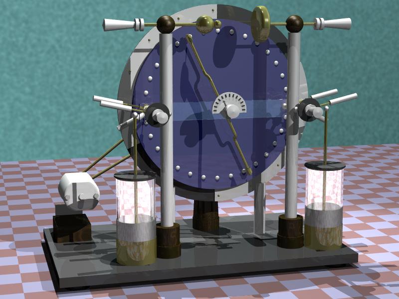
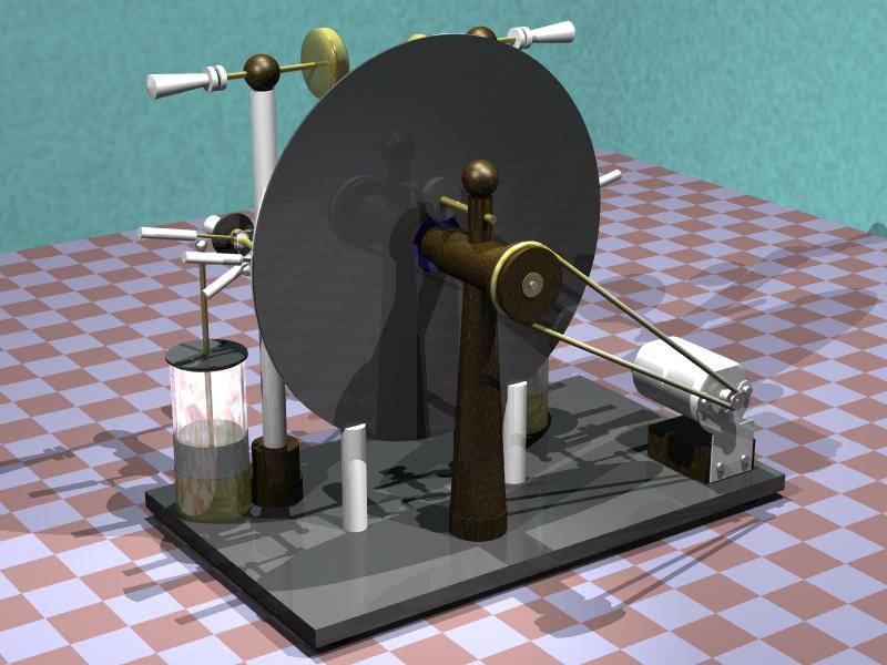
More photos: 12 cm sparks, front view, side view,
back view.
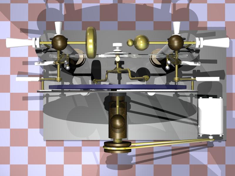
Drawings: Front view, back
view, top view.

12.5 cm sparks
Created: 23/04/2002
Last update: 29/11/2010
Developed and maintained by Antonio Carlos
M. de Queiroz
Return to Electrostatic Machines