The Wommelsdorf Condenser Machine
Introduction
 Heinrich Wommelsdorf was a
researcher that developed a series of electrostatic machines, in
Germany, in the first decades of the XX century. Between 1902 and
1932 he published a series of papers
and patents, mainly describing several
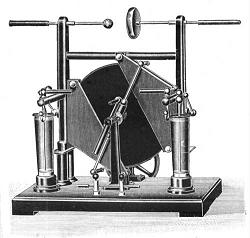
versions of what he named the "Condenser Machine". The
main version of this machine was characterized by a construction
that was similar to a multiplate capacitor,
with rotating disks with internal metal sectors forming one set
of plates, and fixed plates with also internal inductors forming
another set. Electrically, the condenser machine was similar to a
fully sectored Voss, or Toepler-Holtz,
machine, or a Belli machine with charge
collectors separated from the inductors. Wommelsdorf machines
were described in most of the books
dealing with the subject, as particularly efficient and powerful
[1][5][8][26][27]. The final versions
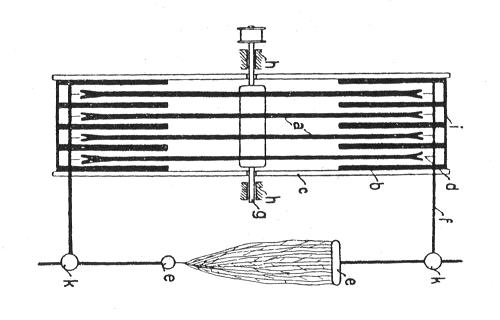
(1920) used an open construction [27]
with ebonite disks with embedded sectors accessed through slots
at their edges, separate inductor plates insulated between
ebonite plates, and a neutralizer circuit having a switch at its
center. This was practically the last of the classical disk
influence machines.
Heinrich Wommelsdorf was a
researcher that developed a series of electrostatic machines, in
Germany, in the first decades of the XX century. Between 1902 and
1932 he published a series of papers
and patents, mainly describing several
versions of what he named the "Condenser Machine". The
main version of this machine was characterized by a construction
that was similar to a multiplate capacitor,
with rotating disks with internal metal sectors forming one set
of plates, and fixed plates with also internal inductors forming
another set. Electrically, the condenser machine was similar to a
fully sectored Voss, or Toepler-Holtz,
machine, or a Belli machine with charge
collectors separated from the inductors. Wommelsdorf machines
were described in most of the books
dealing with the subject, as particularly efficient and powerful
[1][5][8][26][27]. The final versions
(1920) used an open construction [27]
with ebonite disks with embedded sectors accessed through slots
at their edges, separate inductor plates insulated between
ebonite plates, and a neutralizer circuit having a switch at its
center. This was practically the last of the classical disk
influence machines.
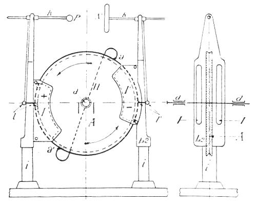
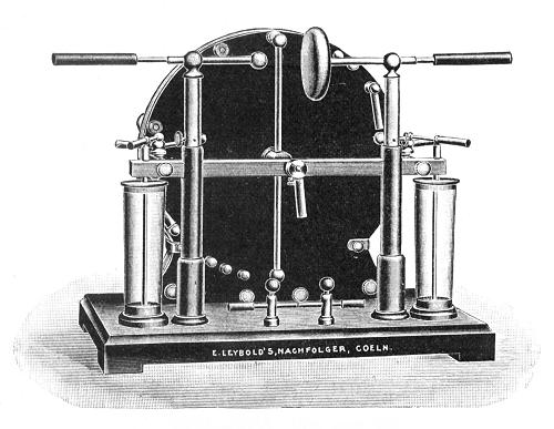
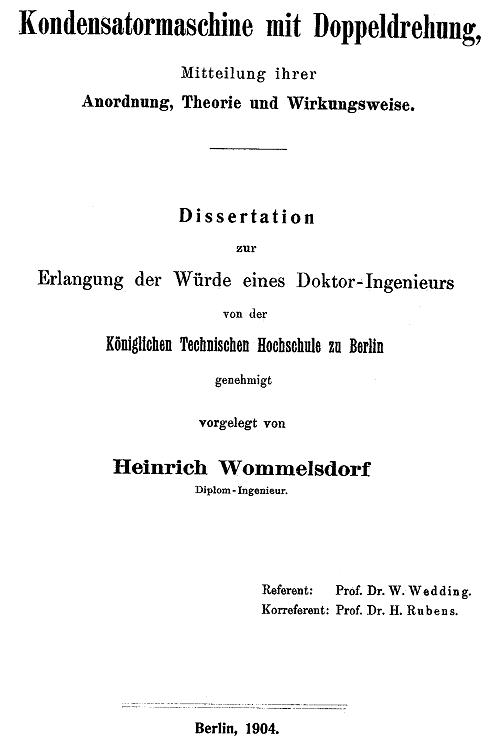
Wommelsdorf described several variations of this machine along
the years, including totally enclosed
machines, and machines with double rotation,
similar to multiple Wimshurst machines, that were the subject of
his Dr. Ing. thesis. He also developed
Wimshurst triplex machines. Another
interesting machine that he developed was known as the Wehrsen machine, after the instrument
builder that popularized it. It was a kind of Holtz machine with a disk with embedded
sectors accessed through buttons in front of the machine.
Wommelsdorf had a firm named "Berliner
Elektros Gesellschaft M.B.H.", that produced his
machines under the brand name "Wommella".
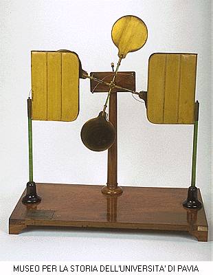
Three Wommelsdorf machines can be seen at the Museo de
Fisica, at the University "La Sapienza", in Rome,
Italy. In May 2000 I made a visit to that museum, and could
observe the machines in detail. Some items were impossible to
observe, as the internal construction of the disks and inductors,
but these could be deduced from the old texts. I then decided to
build one. This would not be a simple project, as the structure
of the machine is rather complicated. But I wanted to see if all
that complication can lead to significant gains in performance
over, for example, a simpler Voss machine.
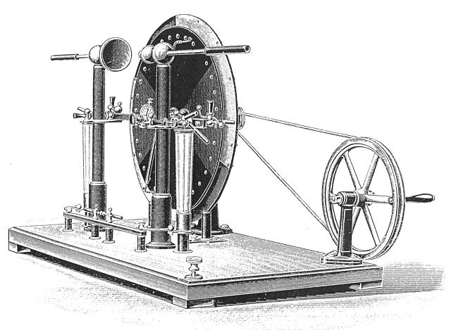
Construction
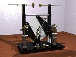 I
started by October 2000, deciding for a
double machine, with two rotating disks and three pairs of
inductor plates. The structure would be similar to the structure
of the double machine seen in Rome, that also appears in the book by F. Luscia [27], with
some small modifications and adaptations. The machine would not
be large, with the rotating disks having 28 cm of diameter, but I
made it with enough insulation for a maximum spark length of 20
cm (data about old machines suggested
that this would be possible), with expected output current of at
least100 µA. I wanted to see if the doubled inductors and the
two sections really increase the output current, and by how much.
I
started by October 2000, deciding for a
double machine, with two rotating disks and three pairs of
inductor plates. The structure would be similar to the structure
of the double machine seen in Rome, that also appears in the book by F. Luscia [27], with
some small modifications and adaptations. The machine would not
be large, with the rotating disks having 28 cm of diameter, but I
made it with enough insulation for a maximum spark length of 20
cm (data about old machines suggested
that this would be possible), with expected output current of at
least100 µA. I wanted to see if the doubled inductors and the
two sections really increase the output current, and by how much.
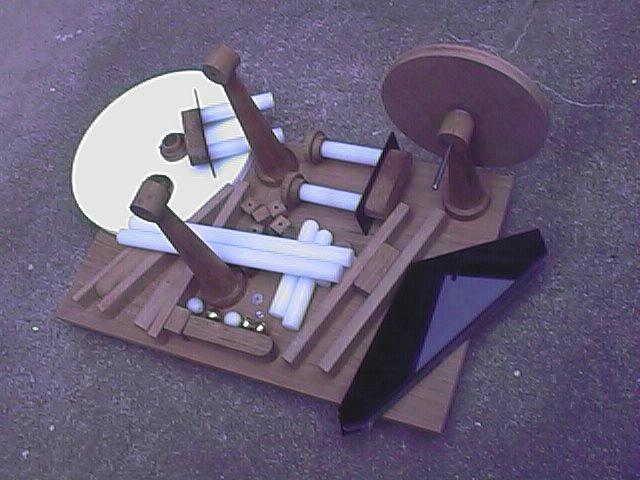
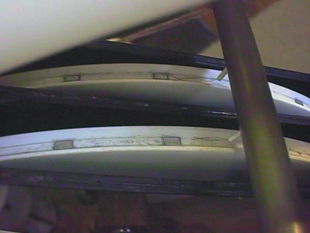
I made the disks as a stack of three white acrylic disks with
2.5 mm of thickness, glued with epoxy (Araldite) glue. In the
central disk, that have smaller diameter (27.5 cm), I fixed 32
sectors made of adhesive aluminum foil, 16 at each side,
anternately. The sectors, 6 cm long, at 0.5 cm from the edge of
the central disk, have a thin 0.5 cm tab folding over the edge of
the disk, being the only area of the sectors exposed for contact.
The sectors cover most of the active area, but the central disk
keeps the sectors well insulated one from the other. The glue
completes the insulation. The outer disks have an inclined cut at
the edge, and so the assembled disks have a groove
at the edge, where brushes can make contact with the internal
sectors.
I made the inductors plates with paper, with a central
aluminum foil strip, sandwiched between pairs of black acrylic
plates 2.5 mm thick, glued with epoxy glue. They are accessed
only through small holes in the plates. The internal inductors
were kept at 8 mm from the edges of the plates, following their
external shape, ending at a few cm from the supports of the
plates.
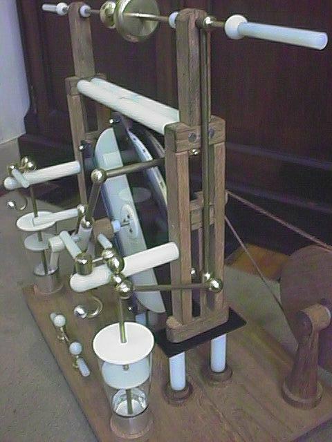
This machine has a curious construction, with two lateral
structures made of wood, directly connected to the high voltage
and insulated from the base by two insulating feet and a flat
plate each and one from the other by two long horizontal bars
above, that complete the structure. I made the complicated
lateral structures with several wood
bars and blocks each joined by screws. The insulators were made
with 2 cm Nylon rods and black acrylic plates, with the feet
fixed to the base with threaded rods and nuts through turned wood
bases, and the horizontal bars fixed by screws. The inductor
plates are fixed to these lateral structures, to the horizontal
bars, and to insulating supports below, by wood blocks, threaded
rods and blind nuts.
The axle for the disks is made from a 6 mm steel bar (taken
from a discarded printer) supported by two turned wood supports,
made in two parts: Conical vertical
supports, and horizontal cylinders with ball bearings. The
disks are fixed to the axle by a central cylindrical Nylon block
where they are screwed by three screws each, and small acrylic
disks to distribute the pressure. The block is fixed to the axle
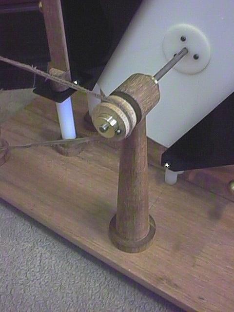
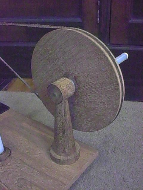
by a set screw. The axle is moved by a pulley system, with a
small pulley in the axle and a large pulley
with a crank at the back of the machine. The speed multiplication
in the pulley system is of about 5.6 times (I started with 10
times, but the leather cord was slipping excessively in the small
pulley).
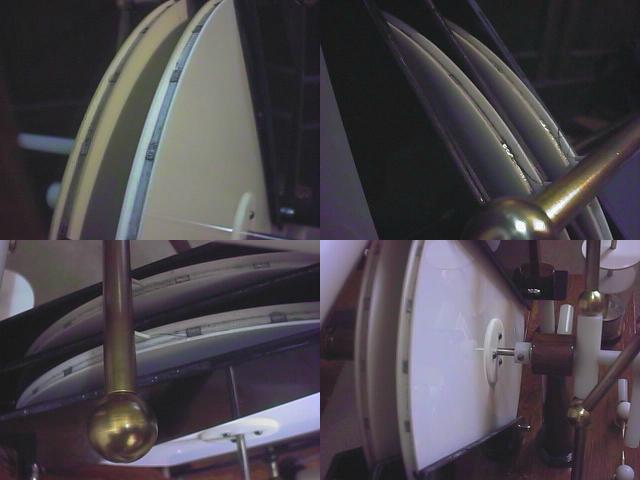
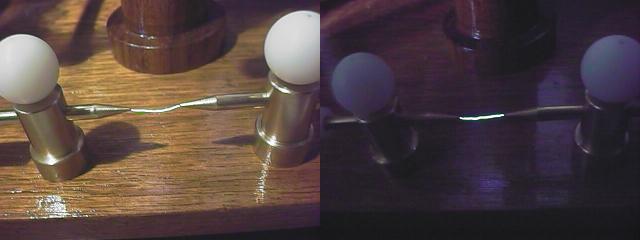
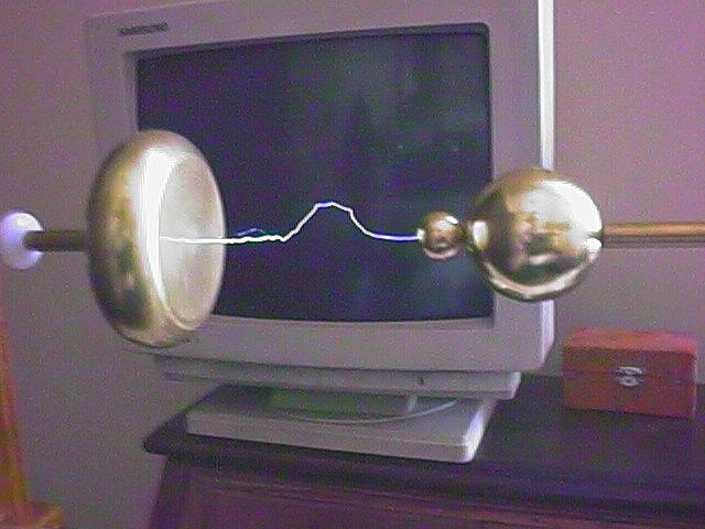
The terminals were made by metal spinning.
One is a ball, and the other a rounded disk. They are screwed to
1/4" brass bars that slide within tubes mounted in the
lateral structures. The tubes end in rounded flanges that support
the bars, the outer ones made of brass and the inner ones in
Nylon. The tubes are connected by screws to vertical brass bars
that connect to the charge collectors below.
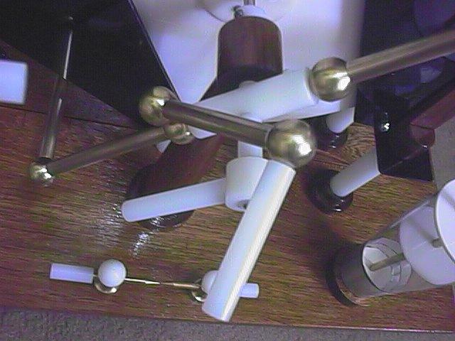
The machine has in front of it a complicated network of switches. Two levers at the sides connect
the charge collectors to the Leyden jars, and two switches
connect the Leyden jars to hooks that serve for external
connections. The frontal assemblies are supported by two 2 cm
Nylon bars. The switches were made with brass rods, rounded
cylinders, and 10 solid brass balls (that I turned in the lathe).
The bars, balls, and Nylon handles are interconnected by sections
of 3/16" threaded rod. The pivots for the switches are
3/16" brass rods with longitudinal slots, that plug into
holes in balls or rounded cylinders.
The fixed Leyden jars were made from
plastic beer glasses. I removed their bases (that were separate
parts) and made simple wood supports, fixed to the base by
threaded rods, washers, and nuts, in a way that allows some
freedom for adjustments in the position of the bases. The outer
plates of the jars (aluminum foil) touch strips of aluminum foil
at the bases, that connect to the rods that fix the bases. Wires
below the base connect the Leyden jars to a point
spark gap in front of the machine, where connections for
pulsed output can be taken. The inner plates of the Leyden jars
connect to vertical bars that go to the switch assemblies. The
jars can be easily dismounted by unscrewing a ball with a
threaded rod in the switch assemblies.
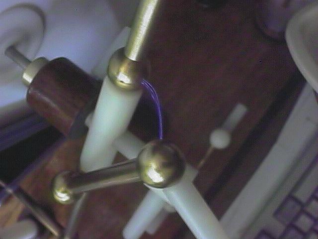
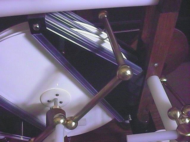
The neutralizer is another
complicated assembly of brass tubes, Nylon cylinders, and 8 brass
balls, interconnected by internal threaded rods. Brushes made of
nickel-chrome wire touch the sectors of the disks, and are put in
contact through a switch in the middle of the assembly. An
insulated handle allows the rotation of the neutralizer with the
machine running and the switch open (there is high voltage in the
bars in this condition). The neutralizer is fixed to a short
steel bar that inserts in the frontal upright support. A screw
with a handle at the side of the support allows the fixation of
its position.
All the brushes were made with thin nickel-chrome wires, just
2 to 4 wires per brush. The wires were simply inserted in thin
plastic tubes made from wire insulation, folded to be exposed at
the outer side of the tubes for electrical contact. The tubes
were then inserted in holes in the switch supports, remaining
there by pressure. The plastic tubes help in keeping the brushes
in the grooves and turn them more resistant to breaking. There
are 4 brushes in the neutralizer, 4 in
the charge collectors, and two appropriating brushes, that charge
the two frontal pairs of inductor plates. These brushes are
mounted in short horizontal metal rods, insulated by acrylic
blocks fixed to the wood structure, that touch contact buttons
with springs at the surfaces of the inductor plates. The back
pair of inductors is charged by brushes that take charge from the
surface of the back disk, as in a Holtz
machine. For symmetry, I added a corresponding pair of these
"Holtz brushes" in the central pair of inductors too.
The brushes are mounted in metal buttons that make contact with
the inductors. I didn't find any document describing this system,
but the same system is apparently used in the machines in Rome.
The Holtz brushes and the charge collector brushes don't actually
touch the disks, but are kept close to them. The others must
touch or the machine doesn't start by itself.
Finally, I varnished all the wood parts with several layers of
polyurethane varnish and lacquered the metal parts with shellac
varnish.
Performance
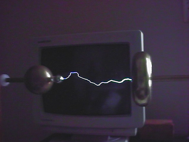
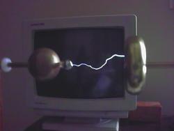 I
could test the machine in the first days of 2001. Initially I had
to solve problems with startup difficulty (bad contacts in the
appropriating brushes) and the driving cord slipping in the small
driving pulley (I made a larger one). The first observation was
that the spark length was rather low. With the installed
terminals no more than 3.5 cm sparks
were obtained. I could increase this to 8
cm adding a smaller (9 mm) ball in series with the ball
terminal, separated by a short plastic tube. The same trick that
I have to use to make my Holtz and Voss machines produce long sparks in humid
air. A single smaller ball in the ball terminal was also useful.
The disk terminal for the negative side is efficient. Balls there
only reduce the spark length. The maximum short-circuit output
current was measured as 40 µA with 2 turns per second at the
crank. This is close to the expected output
current of four Wimshurst machines with the same sectors (16
per disk, covering ~1/2 of the active area) and speed. Varying
the rotation speed, the current varies in approximately linear
proportion, but with significant losses at low speeds. The angle
of the neutralizer affects a bit the current, with maximum
current at low angle. I was expecting a current close to this
value, or somewhat larger. The calculation is as follows:
I
could test the machine in the first days of 2001. Initially I had
to solve problems with startup difficulty (bad contacts in the
appropriating brushes) and the driving cord slipping in the small
driving pulley (I made a larger one). The first observation was
that the spark length was rather low. With the installed
terminals no more than 3.5 cm sparks
were obtained. I could increase this to 8
cm adding a smaller (9 mm) ball in series with the ball
terminal, separated by a short plastic tube. The same trick that
I have to use to make my Holtz and Voss machines produce long sparks in humid
air. A single smaller ball in the ball terminal was also useful.
The disk terminal for the negative side is efficient. Balls there
only reduce the spark length. The maximum short-circuit output
current was measured as 40 µA with 2 turns per second at the
crank. This is close to the expected output
current of four Wimshurst machines with the same sectors (16
per disk, covering ~1/2 of the active area) and speed. Varying
the rotation speed, the current varies in approximately linear
proportion, but with significant losses at low speeds. The angle
of the neutralizer affects a bit the current, with maximum
current at low angle. I was expecting a current close to this
value, or somewhat larger. The calculation is as follows:
The total area of the sectors in one disk is calculated as
0.035 m2. When the sectors leave the inductor plates,
they are equally charged, and so there is no electric field
between the disks. Considering the maximum electric field in air
as 30 kV/cm, the maximum charge density at the outer surface is
the sectors is calculated as 26.55 µC/m2. The disks
turn at 11.2 turns/second with 2 turns/second at the crank.
Considering that the same occurs with opposite polarity at the
other side, and assuming low the current trough the neutralizers
with the output in short-circuit, the charge transferred to the
charge collectors by the two disks per second, that is, the
maximum output current, is obtained as: i = 2 x 2 x 11.2 x
26.55e-6 x 0.035 = 41.6 µA. The first doubling is due to the two
disks, and the other due to polarity reversal at the collectors.
I made measurements with other configurations too, all at 2
turns/second at the crank, obtaining:
a) 1 disk, 1 pair of inductors: 8 µA.
b) 1 disk, 2 pairs of inductors: 17 µA
c) 2 disks, 1 pair of inductors between them: 20 µA
d) 2 disks, 1 pair of inductors between them and another pair at
one side: 29 µA.
e) 2 disks, all 6 inductors: 37-40 µA.
The cases (a), (b), and {c} appear to indicate that only about
1/2 of the maximum current for those configurations is being
generated. A possible reason is the assembly of the disks, where
the sectors are intercalated at both sides of a rather thick
central disk. The glue, that is not a very good insulator, may be
also shielding the sectors from the influence from the most
distant inductor. The effect is the reduction of the area used
for charge transport by 1/2. Case (d) is consistent with this.
All the measurements were made between one terminal and the
neutralizer, kept grounded. Practically the same results can be
obtained by measuring the current directly across the output
terminals, but the machine becomes more difficult to start in
this way.
Similar results, in proportion, were obtained in tests made
with another machine of this type,
larger (built by Serge Klein, in France, in 2000). I could obtain
up to 90 µA cranking as fast as possible (4-5 turns/second).
This is the same output current of my powerful Triplex machine. The old tables showing
the performance of these machines, however, list currents that
are significantly larger. Maybe result of very high rotation
speed, what also increases the spark length.
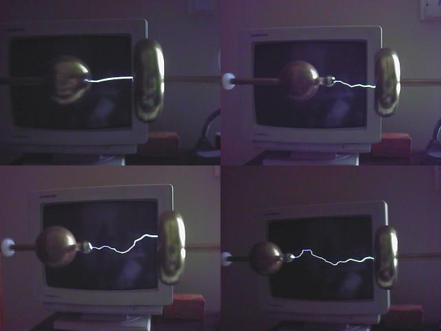
The machine shows periodical polarity reversals, with a period
that decreases with the output voltage. The neutralizer switch
causes an immediate reversal if opened until sparks
cease to cross it (more than 1 cm) and closed again after a
moment. If the switch is left open, the machine stops as soon as
current ceases to flow at the output. These are two useful
functions for the switch. With the output at low voltage, or in
short-circuit, the machine works with the neutralizer switch
open.
The point spark gap produces short
sparks when sparks jump in the main terminals. The distance
there affects the energy of the sparks, and can be used to
control it.
I am not very confident in the insulation properties of the
epoxy glue that I used to seal the disks, and some surfaces may
have been contaminated by humidity before I glued them, but the
insulation of the machine is not specially good, anyway. The
Nylon insulators are rather hygroscopic, and the wood structure
may emit corona, specially while unvarnished. The insulation
between the inductors and the output is also small, and may be
the cause of polarity reversals after long sparks, when the
sudden voltage drop at the lateral structures can take some
charge from the inductors. Low-voltage measurements of resistance
shows resistances around 20000 MOhms between adjacent sectors of
the disks, and between the terminals of the machine. These are
quite low values for an electrostatic machine.
Trying to improve the insulation of the machine, I covered the edges of the inductors with
U-shaped plastic strips. This helped, increasing the output
current at high voltages. I noticed also that the machine works
significantly better with larger Leyden jars. Adding a pair of
200 pF jars to the machine, adding to the normal 50 pF jars that
it already had, I could extend the spark length with the normal
terminals to 5 cm, and the spark length with an added small ball
to 11 cm. These sparks were obtained turning the machine very
fast, and with the neutralizer switch widely open, but still
sparking (2 cm or more). The machine produces a burst of sparks
when the ball terminal is positive, reverts polarity, produces a
burst of corona at the ball terminal, and after some time reverts
again, repeating the process. If the neutralizer switch is
closed, sparks are smaller and the reversals occur with longer
period. If it is totally open, the machine reverts polarity at a
fast rate, and sparks are also smaller.
In this first version, the machine was prejudiced by the
relatively low resistivity of the glue used to seal the disks and
inductors. It worked reasonably well when run at high speed, when
its high output current compensates for the losses, but startup
was problematic. Comparing it with my other machines with disks
of this same size, its performance was just regular. Current was
as expected and the spark length, although smaller than expected
due to losses, was as high as in the other machines. The frequent
polarity reversals were a problem, probably caused by
insufficient insulation between the inductors and the terminals,
but this is almost impossible to avoid in a machine with fixed
inductors.
Improvements in the design would start by better insulation,
using a different system for sealing the disks and inductors, and
by replacing the Nylon insulators. The distances between the
disks and the inductors could be smaller, or adjustable, so an
optimum value could be located. They are at about 5 mm, what
looks high for a machine of this size, but I believe that smaller
distance would only result in quicker startup, with larger
distances resulting in longer time between polarity reversals.
The distances in the original machines were also large. The
distances between the disks and the inductor supports could be
increased for better insulation. The frontal switches could be
longer, to free the connection hooks from the Leyden jars that
are partially below them. The central disk of the disk assemblies
could be thinner, for more uniform electric field at both sides
of the sectors. The Leyden jars could be larger.
Improvements
I made a new terminal ball, a bit smaller and with a small
brass ball (1.2 cm of diameter) directly fixed with a screw. The
result was somewhat better than with the glued 9 mm ball, with sparks reaching 12 cm in a dry day. This
kind of terminals, ball-plane terminals, require less voltage
than regular two-balls terminals for the same spark length.
By May 2002 I made several changes in the materials used in
the machine, to improve the insulation. First, I replaced all the
critical insulators, that were made with Nylon rods, by Teflon,
replaced the leather driving cord by a polyurethane cord, and
rebuilt the disks and inductors. I disassembled them, sanded the
surfaces clean, and installed new sectors (a bit smaller in
width) and inductor plates. The disks I sealed with hot glue,
applying beads around the sectors with a glue application tool
and remelting the glue in an oven, with the disk assemblies
pressed between glass plates. This resulted in some deformation
of the acrylic plates, mostly shrinkage, but the disks were still
usable, and now with good insulation. I didn't glue the inductor
plates, but just covered the paper and metal inductors with two
layers of adhesive plastic foil, leaving them between the two
plates that form each inductor. The insulation obtained in this
way was not enough, and the machine could not generate sparks
with more than 4 cm until I reinstalled the covers at the edges
of the inductors. With this the machine exceeded its previous
performance, reaching 13.5 cm sparks easily, and 50 µA of output
current at 2 turns per second at the crank. The maximum current,
limited by practicable cranking speed, easily exceeds 100 µA.
Some differences in operation were also observed. The machine
works even with the neutralizer switch completely open, and takes
longer time to revert polarity, even with its regular Leyden
jars. The machine is quite powerful now, although very easy to
crank.
Further improvements would be to make new disks, sealed with
something that doesn't cause deformation of the acrylic plates,
and maybe to make also new inductors, adequately sealed, to
eliminate the edge covers. It's interesting to note that the
ebonite disks on old machines that I have seen appear to have
been made with the groove at the edge machined after the disks
were built. The edges of the internal sectors were visible in the
groove, being enough for contact. The inductor plates were not
glued, but had thick insulating plates folded over the edges.
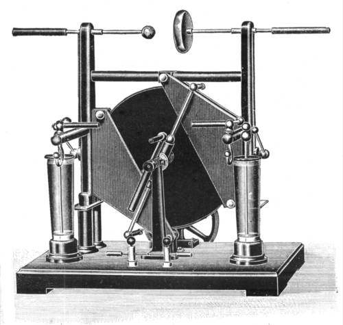
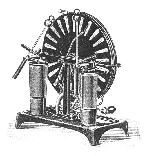
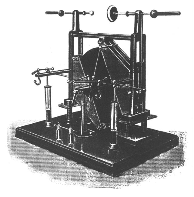
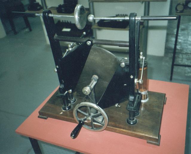
An old machine
In June 2001 I found an old Wommelsdorf machine in a museum at
the Federal University of Juiz de Fora (Juiz de Fora, Minas
Gerais, Brazil). It is a small machine with a single 26 cm disk,
of the "Wommella" brand, almost identical to the classic machine described by Wommelsdorf
in 1920 [p84]. These pictures show a frontal view and a back
view of it. The lateral vertical supports and the base are
made of wood, with two ebonite insulators at each side and an
horizontal ebonite bar above the disk, Two ebonite arms at the
sides support the Leyden jars and output switches. No hook is
present below the switches. Switches connect the charge
collectors to the leyden jars. The output terminals, a ball and a
disk, are directly connected to the charge collectors through
insulated bars. The disk and the insulators are made of ebonite.
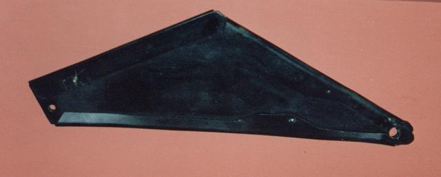
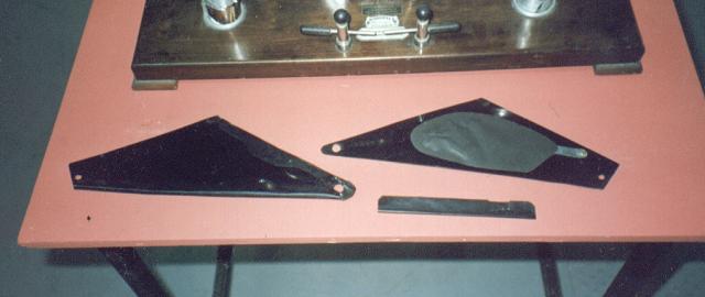
The inductors are made from a flexible
black material, not very thick, possibly celluloid. They are not
sealed, but composed of three pieces,
one forming a kind of outer envelope, involving an inner plate,
and a section insulating the outer edge from the machine wood
structure. In the inner plates there are paper inductors, glued,
covering metal strips ending in pins that cross the insulating
plates, that are to be inserted in holes in the ebonite structures holding the appropriating
brushes. The inductors are held in place by thumb screws, fixed
to ebonite blocks mounted in the lateral structures, to the upper
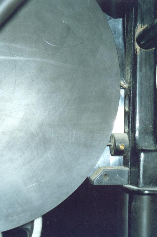
horizontal bars, and to a block in the base. The brushes are all
made of thick bunches of thin metal blades. The charge collectors
brushes are mounted directly in the wood structure. The machine
was not in working conditions, but restorable.
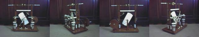
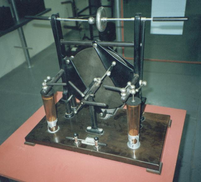
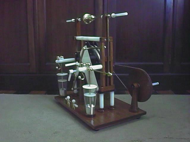
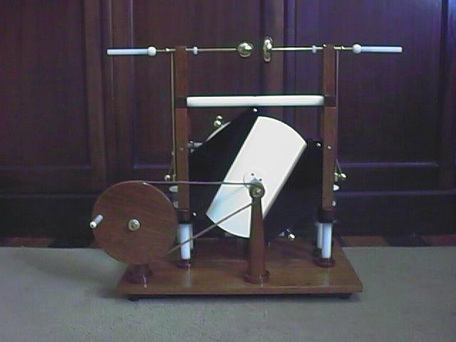
My machine: Front view,
right side, back
view, left side.
Created: 27/01/2001
Last update: 09/01/2003
Developed and maintained by Antonio Carlos
M. de Queiroz
Return to Electrostatic Machines
