

| SimPowerSystems | |
Building and Simulating the PWM Motor Drive
Assembling and Configuring the Motor Blocks
In the first steps, you copy and set up the motor blocks.
circuit5.
circuit5 model.
Power Electronic device = IGBT/Diodes; Port configuration= ABC as output terminals; Snubber Rs=1e5 W Cs=inf; Ron=1e-3 
; Tail: Tf=1e-6s; Tt=1e-6 s
Notice that the snubber circuit is integral to the Universal Bridge dialog box. As the Cs capacitor value of the snubber is set to Inf (short-circuit), we are using a purely resistive snubber. Generally, IGBT bridges do not use snubbers; however, because each nonlinear element in the Power System Blockset is modeled as a current source, you have to provide a parallel path across each IGBT in order to allow connection to an inductive circuit (stator of the asynchronous machine). The high resistance value of the snubber does not affect the circuit performance.
circuit5 model.
a, b, and c are accessible. During normal motor operation these terminals should be short-circuited together. Open the Connectors library. Copy the vertical Bus Bar block with two inputs and one output into your circuit5 model.
is_abc (three stator currents), wm (rotor speed), and Te (electromagnetic torque).
Loading and Driving the Motor
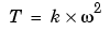
You now implement the torque-speed characteristic of the motor load. Assume a quadratic torque-speed characteristic (fan or pump type load). The torque T is then proportional to the square of the speed  .
.
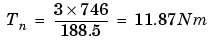
The nominal torque of the motor is
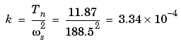
Therefore, the constant k should be
circuit5 model. Open the block menu and enter the expression of torque as a function of speed.
wm and its output to the torque input of the motor labeled Tm.
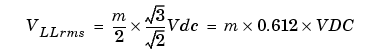
circuit5 model. Open the block menu and set the voltage to 400 V.
circuit5 model. Change the block name to Vab.
Controlling the Inverter Bridge with a Pulse Generator
In order to control your inverter bridge, you need a pulse generator. Such a generator is available in the Extras library of powerlib.
circuit5 model. Connect its Pulses output to the Pulses input of the Universal Bridge block.
Generator Mode = 3-arm bridge (6pulses); Carrier frequency = 1080 Hz; Sample time = 10e-6 s; Internal generation of modulating signal = checked; Modulation index m = 0.9; Frequency of output voltage = 60 Hz; Phase of output voltage = 0 degrees
Therefore, a DC voltage of 400 V and a modulation factor of 0.90 yield the 220 Vrms output line-to-line voltage, which is the nominal voltage of the asynchronous motor.
circuit5 model.
is_abc output of the ASM Measurement Demux block.
Open its menu and set Element to 1. Connect the Selector output to the second Fourier block and its input to the is_abc output of the Machines Measurement Demux block as shown in Figure 1-13.
Number of axes=4; Time range =0.05 s; Tick labels: bottom axis only
Connect the four inputs and label the four connection lines as shown in Figure 1-13. When you start the simulation, these labels are displayed on top of each trace.
Simulating the PWM Motor Drive with Continuous Integration Algorithm
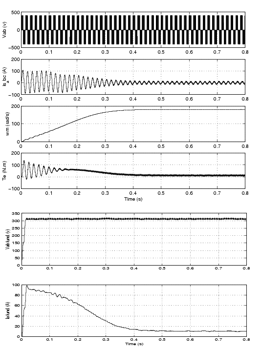
Open the Simulation --> Simulation parameters menu. Select the ode23tb integration algorithm. Set the relative tolerance to 1e-4, the absolute tolerance and the Max step size to auto, and the stop time to 1 s. Start the simulation. The simulation results are shown in Figure 1-14.
The motor starts and reaches its steady-state speed of 181 rad/s (1728 rpm) after 0.5 s. At starting, the magnitude of the 60 Hz current reaches 90 A peak (64 A rms) whereas its steady-state value is 10.5 A (7.4 A rms). As expected, the magnitude of the 60 Hz voltage contained in the chopped wave stays at
Also notice strong oscillations of the electromagnetic torque at starting. If you zoom in on the torque in steady state, you should observe a noisy signal with a mean value of 11.9 N.m, corresponding to the load torque at nominal speed.
If you zoom in on the three motor currents, you can see that all the harmonics (multiples of the 1080 Hz switching frequency) are filtered by the stator inductance, so that the 60 Hz component is dominant.
Figure 1-14: PWM Motor Drive; Simulation Results for Motor Starting at Full Voltage
| | Session 5: Simulating Motor Drives | Using the Multimeter Block | |
 .
.