| SimPowerSystems |
  |
Using the Multimeter Block
You probably have noticed that the Universal Bridge block is not a conventional subsystem where all the six individual switches are accessible. If you want to measure the switch voltages and currents you must use the Multimeter block, which gives access to the bridge internal signals.
- Open the Universal Bridge dialog and set the Measurement parameter to
Device currents.
- Copy the Multimeter block from the Measurements library into your
circuit5 circuit. Double-click the Multimeter block. A window showing the six switch currents appears.
- Select the two currents of the bridge arm connected to phase A. They are identified as
iSw1: Universal Bridge
iSw2: Universal Bridge
- Click OK. The number of signals (2) is displayed in the multimeter icon.
- Using a Demux block, send the two multimeter output signals to a two-trace scope and label the two connection lines as shown in Figure 1-13 (Trace 1:
iSw1 Trace 2: iSw2).
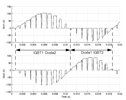
- Restart the simulation. The waveforms obtained for the first 20 ms are shown in this plot.

Figure 1-15: Currents in IGBT/Diode Switches 1 and 2
As expected, the currents in switches 1 and 2 are complementary. A positive current indicates a current flowing in the IGBT, whereas a negative current indicates a current in the antiparallel diode.
| Note
Multimeter block use is not restrained to the Universal Bridge block. All the elements of the Electrical Sources and Elements libraries have a Measurement parameter where you can select voltages, currents, and saturable transformer fluxes. A judicious use of the Multimeter block reduces the number of current and voltage sensors in your circuit, making it easier to follow.
|
 | Building and Simulating the PWM Motor Drive | | Discretizing the PWM Motor Drive |  |


