
| SimMechanics |   |
Configuring a Joint Block
A machine is made up of Bodies with geometric and mass information. But Bodies carry no information of how they move. The possible directions of motion that a Body can take are called its degrees of freedom (DoFs), and this section explains how you represent these DoFs by Joint blocks:
One (but not both) of the members of such a pair of Bodies can be a Ground. The other member Body of such a pair then has its motion defined relative to a fixed ground point. This fixed ground point does not have to be the same as the World origin. A machine can have many such Ground-Body pairs and must have at least one.
How to Connect a Joint Between Two Bodies
You represent relative motion of bodies with respect to one another by connecting their Body blocks with Joints. You can connect a Body to one or more Joints.
A Joint block is always connected to a specific point on the Body on either side of the Joint. The specific point for anchoring a Joint on a Body is the origin of a Body CS, and a Joint is therefore connected on one side to one Body at a Body CS origin, and on the other side to the other Body at a Body CS origin.
Usually a Body is connected to a Joint on either side, so the default you saw earlier in this tutorial for Body CSs in the Body dialog box is three Body CSs: the CS at the center of gravity (CG) and two other CSs (CS1 and CS2). But a Body at the end of a Body--Joint--...--Body chain is connected to only one Joint.
Revolute Joint for the Simple Pendulum
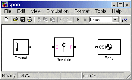
In spite of the complexity of the concepts implicit in a Joint, the actual configuration of a Joint block is fairly simple. Here you insert and configure one revolute Joint block between the Ground and Body blocks you've already put into the model window.
Figure 2-3: Simple Pendulum Connected to Ground via Revolute
Configuring the Revolute Joint Block. The geometry of the Joint connection is shown in Figure 2-3. The ground point at (3,4,5) and the CS1 at (3,4,5) are actually the same point in space, but have been separated in the figure for clarity. The revolute rotation axis is along the +z direction:
GND@Ground, which is the Grounded CS associated with the Ground block located at (3,4,5) in World.
CS1@Body, which is the CS1 on Body1 located at (3,4,5) in World.
Congratulations -- you have now finished the simplest possible model of a machine: a connected block diagram of Ground--Joint--Body. Your model window should look like this.

 | Configuring the Body Dialog | Adding Sensors and Starting the Simulation |  |