| SimMechanics |
  |
Configuring the Body Dialog
Take the steps to configuring a Body block dialog box in several stages.

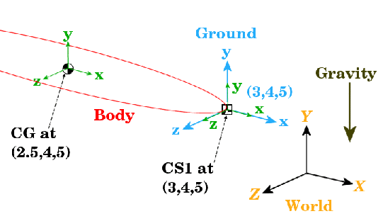
Figure 2-2: Equivalent Ellipsoid of Simple Pendulum with Coordinate Systems
Adding the Body Block. To start working with the Body block:
- Open the Bodies library in the SimMechanics library.
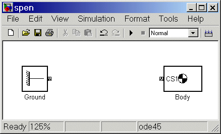
- Drag and drop a Body block into your model window.
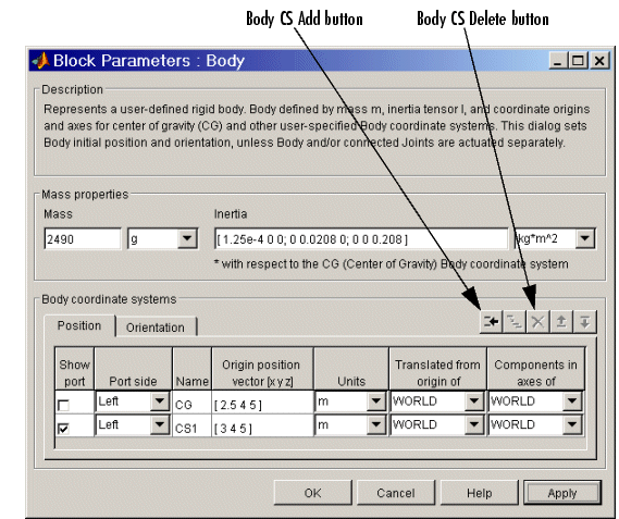
- Open the Body block dialog box. Note the two main areas you need to configure:
- Mass properties -- These are the mass and inertia tensor.
- Body coordinate systems -- These are the details about the position and orientation of the Body CSs.
| Note
To apply your dialog entries at any time, click Apply. To close a dialog, click OK.
|


Configuring the Body's Mass Properties. Now enter the body's mass and inertia tensor:
- Use the data from the table Body Data for the Simple Pendulum.
- In the Mass field, enter
2490 and change the units to g (grams).
- In the Inertia tensor field, enter
[1.25e-4 0 0; 0 0.208 0; 0 0 0.208] and leave the default units as kg-m2.
Configuring Body Coordinate Systems (Position). Configure the translational position of the body and its Body CS origins in space:
- Use the data from table Body Data for the Simple Pendulum, and work on the Position pane. Vectors are assumed translated from the World origin and oriented to the World axes.
- Note the three default CSs in the Body dialog box. The CS at the CG is necessary for any Body, and you will connect CS1 to the Ground with a Joint shortly.
- Delete CS2 by selecting its line in the Body CS list and clicking the Delete button in the Body CS controls.
You have two already existing CSs not on this Body that you can use to specify the positions of the Body CS origins that are on this Body:
- Preexisting World origin at
[0 0 0]
- The Adjoining CS on the neighboring body, in this case the Grounded CS origin at
[3 4 5]
- Specify the CG and CS1 origins relative to World:
- In the pull-down menu under Translated from origin of, choose
World
for both CSs: CG and CS1.
- Under Origin position vector, specify the position of the origin of each
CS, translated from the World origin:
-
[3 4 5] for CS1
[2.5 4 5] for CG
- Select a CS relative to whose coordinate axes the components of the vectors in the last step are measured. You choose these CS axes in the Components in axes of menu. Select
World for both CSs. Leave the units as m (meters).
Configuring Body Coordinate Systems (Orientation). Configure the rotational orientation of the body and its Body CS axes in space:
- Work on the Orientation pane. The default orientation for all CS axes is parallel to World. The sign of all rotations is determined by the right-hand rule.
- Notice in Figure 2-2 that the CS1 and CG axes are oriented parallel to the World axes, so the CS1 and CG axes need no rotation.
- For both CSs, set the Relative to coordinate system menu to
World.
- For CG and CS1, leave the Orientation vector at default
[0 0 0] and the Specified using convention at default Euler X-Y-Z. Close the Body dialog.
 | Configuring a Body Block | | Configuring a Joint Block |  |


