| Embedded Target for Motorola MPC555 |
  |
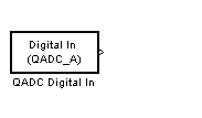
QADC Digital In
Input driver enables use of Queued Analog-Digital Converter (QADC64) pins as digital inputs
Library
Embedded Target for Motorola MPC555
Description

The QADC Digital In block allows you to treat the QADC64 pins as digital inputs. Each QADC64 module has two 8-bit ports, A and B. You can use any bit on either port as a digital input.
Dialog Box

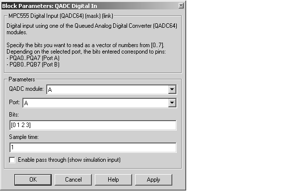
- QADC module
- Selects module A or B.
- Port
- Selects an 8 bit port (A or B) on the module.
- Bits
- A vector of bits (numbered 0-7) to read. The vector should not be longer than eight elements.
- Sample time
- Block sample time; determines sample rate at which the port is monitored.
- Enable pass through (show simulation input)
- Lets you provide a signal to this block for use in simulation. When this option is enabled, an inport appears on the block. The block input is passed through, unaltered, to the output during simulation. This option affects simulation only.
Mapping Bits To Hardware Pins
Use Table 5-3 to work out how the block ports and bits map to processor pins on the MPC555.
Table 5-3: Relationship of Port/Bit Parameters to Hardware Pins
Port
|
Bit
|
Hardware Pin
|
B
|
0
|
A_AD0 / PQB0
|
B
|
1
|
A_AD1 / PQB1
|
B
|
2
|
A_AD2 / PQB2
|
B
|
3
|
A_AD3 / PQB3
|
B
|
4
|
A_AD4 / PQB4
|
B
|
5
|
A_AD5 / PQB5
|
B
|
6
|
A_AD6 / PQB6
|
B
|
7
|
A_AD7 / PQB7
|
A
|
0
|
A_AD8 / PQA0
|
A
|
1
|
A_AD9 / PQA1
|
A
|
2
|
A_AD10 / PQA2
|
A
|
3
|
A_AD11 / PQA3
|
A
|
4
|
A_AD12 / PQA4
|
A
|
5
|
A_AD13 / PQA5
|
A
|
6
|
A_AD14 / PQA6
|
A
|
7
|
A_AD15 / PQA7
|
 | QADC Analog In | | TouCAN Error Count |  |


