
| Embedded Target for Motorola MPC555 |   |
Input driver enables use of Queued Analog-Digital Converter (QADC64) in continuous scan mode
Library
Embedded Target for Motorola MPC555
Description
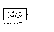
The QADC Analog In block sets the QADC64 into continuous scan mode. It then samples the specified channels at the specified rate. In continuous scan mode, the analog-to-digital converter is scanned as fast as possible, at a rate much faster than the sample rate of the model. Using continuous scan mode ensures that your application will obtain the latest signal value.
The MPC555 has two QADC modules, A and B. You can program these individually. You can place only one instance of the QADC Analog In block per module in your model or subsystem.
Dialog Box
Right-justified (unsigned): with zeros in the higher order unused bits.
Left-justified (signed): with the most significant bit inverted to form a sign bit, and zeros in the unused lower order bits. In this mode, zero is treated as the half scale of the input range.
Left-justified (unsigned): with zeros in the unused lower order bits.
0..1 to represent the minimum and maximum voltage input. This input signal is mapped onto output according to the selected Justification option for justification. The Enable pass through option affects simulation only.Channel Number Selection
A channel number in the Channels vector selects the input channel number corresponding to the analog input pin to be sampled and converted. The analog input pin channel number assignments and the pin definitions vary, depending on whether the QADC64 is operating in multiplexed or nonmultiplexed mode. The queue scan mechanism makes no distinction between an internally or externally multiplexed analog input.
If a reserved channel number (channels 32 to 47) or an invalid channel number (channels 4 to 31 in nonmultiplexed mode), the low reference level (VRL) is converted.
Programming the channel field to channel 63 indicates the end of the queue.
Channels 60 to 62 are special internal channels. When one of these channels is selected, the sample amplifier is not used. Instead, the value of VRL, VRH, or (VRH - VRL)/2 is placed directly into the converter. Programming the input sample time to any value other than two for one of the internal channels has no benefit except to lengthen the overall conversion time.
Table 5-1 and Table 5-2 show the mapping between the channel numbers and the hardware pins for the two scanning modes (multiplexed and nonmultiplexed).
For example, in nonmultiplexed mode, to scan all 16 channels of the QADC64 you would specify the following vector in the Channels field:
In Table 5-2, PQA0, PQA1 and PQA2 are used as output pins to drive an external demultiplexer.
 | MPC555 Resource Configuration | QADC Digital In |  |