
| Embedded Target for Motorola MPC555 |   |
Support device configuration for MPC555 CPU and MIOS, QADC, and TouCAN Submodules
Library
Embedded Target for Motorola MPC555
Description
The MPC555 Resource Configuration block differs in function and behavior from conventional blocks. Therefore, we refer to this block as the MPC555 Resource Configuration object.
The MPC555 Resource Configuration object maintains configuration settings that apply to the MPC555 CPU and its MIOS, QADC, and TouCAN subsystems. Although the MPC555 Resource Configuration object resembles a conventional block in appearance, it is not connected to other blocks via input or output ports. This is because the purpose of the MPC555 Resource Configuration object is to provide information to other blocks in the model. MPC555 device driver blocks register their presence with the MPC555 Resource Configuration object when they are added to a model or subsystem; they can then query the MPC555 Resource Configuration object for required information.
To install a MPC555 Resource Configuration object in a model or subsystem, open the top-level Embedded Target for Motorola MPC555 library and select the MPC555 Resource Configuration icon. Then drag and drop it into your model or subsystem, like a conventional block.
Having installed a MPC555 Resource Configuration object into your model or subsystem, you can then select and edit configuration settings in the MPC555 Resource Configuration window. See Using the MPC555 Resource Configuration Window for further information.
Types of Configurations
A configuration is a collection of parameter values affecting the operation of a group of device driver blocks in one of the Embedded Target for Motorola MPC555 libraries, such as the MIOS1, QADC64 or TouCAN libraries. The MPC555 Resource Configuration object currently supports the following types of configurations:
Active and Inactive Configurations
An active configuration is a configuration associated with blocks of the model or subsystem in which the MPC555 Resource Configuration object is installed. There is always an active MPC555 configuration. For any other configuration type (e.g., QADC, MIOS, or TouCAN), there is at most one active configuration.
Consider this model, which contains a MPC555 Resource Configuration object but no MPC555 device driver blocks.
This model has only one active configuration, for the MPC555 itself, as shown in the MPC555 Resource Configuration window.
When a device driver block is added to the model, an appropriate configuration is created and activated. This figure shows an MIOS Digital Out block added to the model.
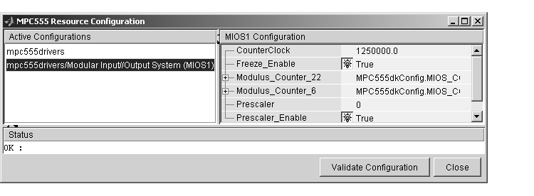
The addition of the MIOS Digital Out block causes an MIOS configuration to be added to the list of active configurations, as shown in this figure.

A configuration remains active until all blocks associated with it are removed from the model or subsystem. At that point, the configuration is in an inactive state. Inactive configurations are not shown in the MPC555 Resource Configuration window. You can reactivate a configuration by simply adding an appropriate block into the model.
When you save a model that contains inactive configurations, you have the option to either save inactive configurations with the model, or delete them.
Using the MPC555 Resource Configuration Window
To open the MPC555 Resource Configuration window, install a MPC555 Resource Configuration object in your model or subsystem, and double-click on the MPC555 Resource Configuration icon. The MPC555 Resource Configuration window then opens.

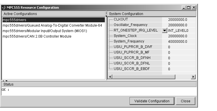
Figure 5-1: MPC555 Resource Configuration Window
Figure 5-1 shows the MPC555 Resource Configuration window for a model that has active configurations for MPC555, MIOS1, QADC, and TouCAN.
The MPC555 Resource Configuration window consists of the following elements:
To see documentation associated with an active configuration, right-click on its entry in the list. From the popup menu that appears, select Help.
| Note There is no Apply or Undo functionality in the System configuration panel. All parameter changes are applied immediately. |
MPC555 Resource Configuration Window Parameters
The sections below describe the parameters for each type of configuration in the MPC555 Resource Configuration window. The default parameter settings are optimal for most purposes. If you want to change the settings, we suggest you read the sections of the MPC555 Users Manual referenced below. You can find this document at the following URL.
http://e-www.motorola.com.
System Configuration Parameters
rt_OneStep function is the basic execution driver of all programs generated by the Embedded Target for Motorola MPC555. rt_OneStep is installed as a timer interrupt service routine; it sequences calls to the model_step function. The RT_ONESTEP_IRQ_LEVEL parameter lets you associate rt_OneStep with any of the available IRQ levels (0..32). For non -interrupt driven operation, select Interrupts Disabled.rt_OneStep function.QADC64 Configuration Parameters
The QADC64 Configuration parameters configure the QADC64 operational mode and supports the blocks in the QADC sublibrary.
The QADC64 performs 10 bit analog to digital conversion on an input signal. Currently the blocks in this library support only the continuous scan mode of operation. In continuous scan mode, the QADC64 is set to run, and then continuously acquires data into its result buffer. Input is double buffered, so the model can read the result buffer at any time to get the latest available signal data.
The MPC555 has two QADC modules, QADC_A and QADC_B. You can program these individually. By default each QADC module has 16 input channels. By attaching an external multiplexer to three of the analog input pins, you can increase the number of possible channels to 41. These pins become outputs from the processor and can act as inputs to an analog multiplexer. The Multiplex Mode parameter determines whether the QADC64 operates in internally or externally multiplexed mode.
Refer to section 13, "Queued Analog-to-Digital Converter Module-64," in the MPC555 Users Manual for detailed information about the QADC64.
In general, you should not need to change any of the settings of the parameters described below from their defaults. The other parameters are advanced settings. Refer to section 13, "Queued Analog-to-Digital Converter Module-64," in the MPC555 Users Manual for information on these settings.
MIOS1 Configuration Parameters
MMCSM Clock Prescaler, the MIOS Pulse Width Modulation and MIOS Waveform Measurement blocks will not work as expected. To change the clock frequency and hence the available resolution of pulse width modulation and waveform measurement, change the Clock Prescaler to a value between 0 and 255. TouCAN Configuration Parameters
The parameters listed below are the same for TouCAN modules A and B. Consult Section 16 of the MPC555 User's Manual before editing the TouCAN configuration parameter defaults.
Mask Configuration Parameters
1 in the mask causes the corresponding bits in the message to be masked out (i.e., ignored).Timing Configuration Parameters
500000.0.Transmission Configuration Parameters
 | MIOS Waveform Measurement | QADC Analog In |  |