| Embedded Target for Motorola MPC555 |
  |
Downloading the Application to RAM
via SingleStep/BDM
In this section, we will use the Wind River Systems SingleStep debugger to download and start the generated Target_ram.out file to RAM on the target system. Target_ram.out contains both code and symbols for use with the debugger.
Do the following before you begin:
- Make sure that you have downloaded boot code to the flash memory of the MPC555. See Configuring SingleStep and Downloading Boot Code.
- Connect the BDM port of your development board to parallel port LPT1 of your host PC.
- Make sure that the jumpers on the phyCORE-MPC555 board are set as described in Phytec Jumper Settings.
- Cycle the power (or perform a hard reset) on your development board to clear the RAM.
To download the generated Target_ram.out file to RAM:
- Start SingleStep using the
SingleStep On Chip (MPC5xx) for RAM shortcut you created previously (see Configure Shortcuts to SingleStep). The Debug dialog opens. Clear the Debug without a file option. Click on the File tab. Then, use the Browse button to locate the Target_ram.out file.

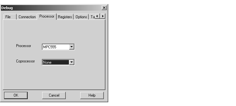
- Click on the Processor tab. Confirm that the
MPC555 is selected in the Processor list, as shown.
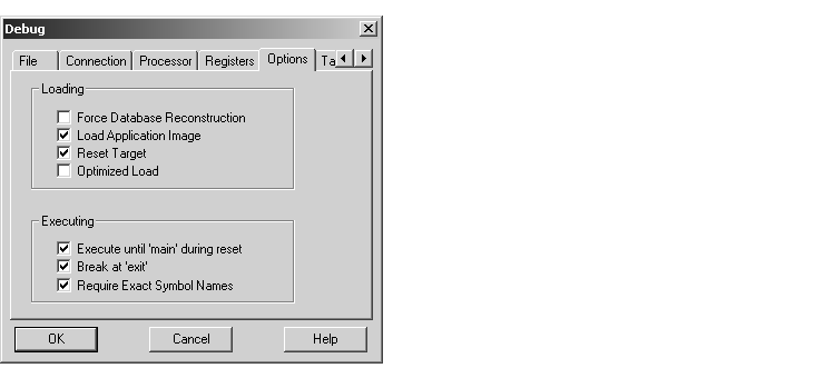
- Click on the Options tab. Make sure that the Reset Target and Load Application Image options are selected, as shown.
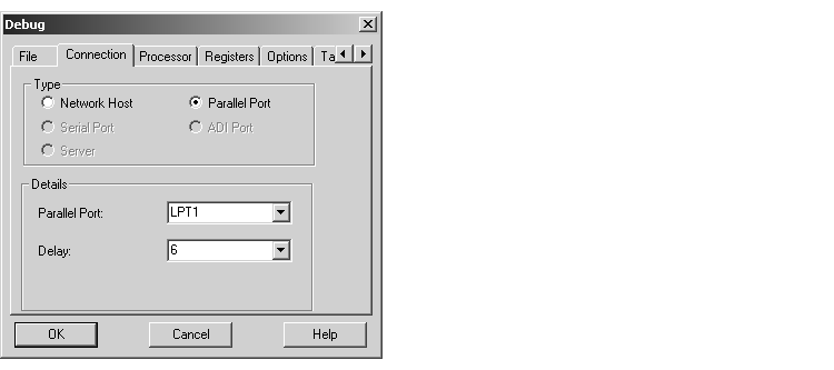
- Click on the Connection tab. Choose parallel port or network settings appropriate to the physical connection you will be using between your PC and PhyCORE-MPC555 board. In the picture below, connection options are configured for the parallel port
LPT1, with a Delay setting of 6.
| Note
We have found that a Delay setting of at least 6 (shown) works best.
|
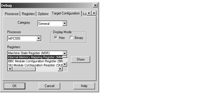
- Click on the Target Configuration tab and select
General from the Category menu. Then select Internal Memory Mapping Register from the Registers menu, as shown.
- Click on the Show button to open the Internal Memory Mapping Register dialog. Clear the FLEN-flash enable option, as shown below.

- Click OK to return to the Target Configuration pane, and select
Base/Option Register 1 from the Registers menu, as shown.
| Note
Be sure to click OK, not Cancel, when closing the Internal Memory Mapping Register dialog box. Otherwise, SingleStep may use different parameter values than those displayed in the dialog box.
|
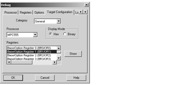
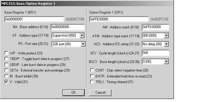
- Click on the Show button to open the Base/Option Register 1 dialog. Set the BA-Base address field to
0x00000000, as shown below.
- Click OK to return to the Target Configuration pane.
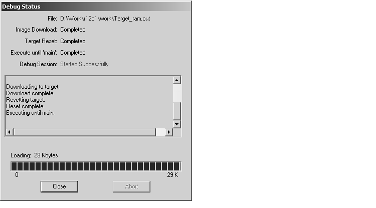
- In the Target Configuration pane, click OK. SingleStep attempts to connect to the processor, and displays a Debug Status window. This picture shows the Debug Status window after a successful connection and download.
- If you see error messages, consult the SingleStep documentation to troubleshoot the connection, or contact Wind River Systems for technical support.
- Click Close to dismiss the Debug Status window.
- At this point, the application code is in RAM, and SingleStep has established a debugging session. To execute the program, click on the green Go button in the SingleStep Debug panel. Observe that the red and green LEDs on the target board are blinking, indicating that the program is running.
- You can now stop, restart, and otherwise exercise the target program via SingleStep.
| Note
Do not reset or cycle power on the board while the target program is running; doing so will hang SingleStep. You must stop the target program before exiting SingleStep.
|
 | Generating Code | | Downloading the Application to RAM via CAN |  |


