| Embedded Target for Motorola MPC555 |
  |
MIOS Waveform Measurement
Purpose
Support pulse width and pulse period measurement via MIOS Double Action Submodule (MDASM)
Library
Embedded Target for Motorola MPC555
Description
Waveform measurement is a feature the MIOS Double Action Submodule (MDASM) on the MPC555. The MIOS Waveform Measurement block currently implements the following features of the MDASM:
- Pulse width measurement: the MIOS Waveform Measurement block outputs the time from the leading edge of a pulse to the trailing edge of the same pulse.
- Pulse period measurement: the MIOS Waveform Measurement block outputs the time from the leading edge of a pulse to the next leading edge of a pulse.
Note that the minimum and maximum measurable pulse periods and pulse widths are dependent on the selected clock sources and their configurations.
You must configure the clock sources via the MPC555 Resource Configuration object. There are only two clock sources (assigned via the Counter bus parameter) assignable to the ten MDASM modules. More than one MDASM can be assigned to a single clock source.
Refer to section 15.11, "MIOS Double Action Submodule (MDASM) Registers" in the MPC555 Users Manual for further information on the parameters described below.
Dialog Box
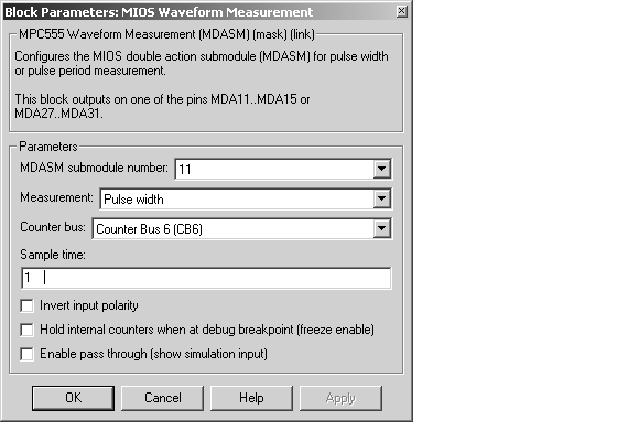
- MDASM submodule number
- Selects one of the 10 MIOS Double Action Submodules in the MPC555.
- Measurement
- Selects the mode of operation of the block: either pulse width measurement or pulse period measurement.
- Counter bus
- Select one of the two counters that can be used as sources to drive the MDASM module.The counters must be configured via the MPC555 Resource Configuration object. See MIOS1 Configuration Parameters.
- Sample time
- The period at which Simulink reads the pulse width or period. The measurements are performed in hardware so it is not necessary to set the sample time to suit the expected period of the incoming signal.
- Invert output polarity
- Changes the sense of the leading edge of the pulse. When Invert output polarity is selected, the leading edge is rising. Otherwise, the leading edge is falling.
- Hold output when at debug break point (freeze enable)
- Stops the clocks of the MDASM module when a breakpoint is hit during debug mode.
- Enable pass through (show simulation input)
- Lets you provide a signal to this block for use in simulation. When this option is enabled, an inport appears on the block. The block input is passed through to the output during simulation. (See Data Type Support and Scaling for Device Driver Blocks for information on supported input/output data types and scaling of input/output signals.) This option affects simulation only.
| | MIOS Pulse Width Modulation Out | | MPC555 Resource Configuration | |