
| DSP Blockset |   |
Store inputs in a FIFO register.
Library
Signal Management / Buffers
Description
The Queue block stores a sequence of input samples in a FIFO (first in, first out) register. The register capacity is set by the Register size parameter, and inputs can be scalars, vectors, or matrices.
The block pushes the input at the In port onto the end of the queue when a trigger event is received at the Push port. When a trigger event is received at the Pop port, the block pops the first element off the queue and holds the Out port at that value. The first input to be pushed onto the queue is always the first to be popped off.
A trigger event at the optional Clr port (enabled by the Clear input check box) empties the queue contents. If Clear output port on reset is selected, then a trigger event at the Clr port empties the queue and sets the value at the Out port to zero. This setting also applies when a disabled subsystem containing the Queue block is reenabled; the Out port value is only reset to zero in this case if Clear output port on reset is selected.
When two or more of the control input ports are triggered at the same time step, the operations are executed in the following order:
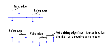
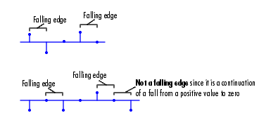
The rate of the trigger signal must be a positive integer multiple of the rate of the data signal input. The triggering event for the Push, Pop, and Clr ports is specified by the Trigger type pop-up menu, and can be one of the following.


| Note When running simulations in the Simulink MultiTasking mode, sample-based trigger signals have a one-sample latency, and frame-based trigger signals have one frame of latency. Thus, there is a one-sample or one-frame delay between the time the block detects a trigger event, and when it applies the trigger. For more information on latency and the Simulink tasking modes, see Excess Algorithmic Delay (Tasking Latency) and the topic on the Simulation Parameters dialog box in the Simulink documentation. |
The Push onto full register parameter specifies the block's behavior when a trigger is received at the Push port but the register is full. The Pop empty register parameter specifies the block's behavior when a trigger is received at the Pop port but the register is empty. The following options are available for both cases:
The Push onto full register parameter additionally offers the Dynamic reallocation option, which dynamically resizes the register to accept as many additional inputs as memory permits. To find out how many elements are on the queue at a given time, enable the Num output port by selecting the Output number of register entries option.
Example 1
The table below illustrates the Queue block's operation for a Register size of 4, Trigger type of Either edge, and Clear output port on reset enabled. Because the block triggers on both rising and falling edges in this example, each transition from 1 to 0 or 0 to 1 in the Push, Pop, and Clr columns below represents a distinct trigger event. A 1 in the Empty column indicates an empty queue, while a 1 in the Full column indicates a full queue.
Note that at the last step shown, the Push and Clr ports are triggered simultaneously. The Clr trigger takes precedence, and the queue is first cleared and then pushed.
Example 2
The dspqdemo demo provides another example of Queue operation.
Dialog Box
Push port when the register is full. Inputs to this port must have the same built-in data type as inputs to the Pop and Clr input ports.Pop port when the register is empty. Inputs to this port must have the same built-in data type as inputs to the Push and Clr input ports. Tunable.Empty output port, which is high (1) when the queue is empty, and low (0) otherwise.Full output port, which is high (1) when the queue is full, and low (0) otherwise. The Full port remains low when Dynamic reallocation is selected from the Push onto full register parameter.Num output port, which tracks the number of entries currently on the queue. When inputs to the In port are double-precision values, the outputs from the Num port are double-precision values. Otherwise, the outputs from the Num port are 32-bit unsigned integer values.Clr input port, which empties the queue when the trigger specified by the Trigger type is received. Inputs to this port must have the same built-in data type as inputs to the Push and Pop input ports.Out port to zero (in addition to clearing the queue) when a trigger is received at the Clr input port. Tunable.Supported Data Types
Push, Pop, and Clr ports. The block may output Boolean values at the Out and Full ports depending on the input data type, and whether Boolean support is enabled or disabled, as described in Effects of Enabling and Disabling Boolean Support. To learn how to disable Boolean output support, see Steps to Disabling Boolean Support.
To learn how to convert to the above data types in MATLAB and Simulink, see Supported Data Types and How to Convert to Them.
See Also
| Buffer |
DSP Blockset |
| Delay Line |
DSP Blockset |
| Stack |
DSP Blockset |
Also see Buffers for a list of all the blocks in the Buffers library.
 | QR Solver | Random Source |  |