| DSP Blockset | |
Count up or down through a specified range of numbers.
Library
Signal Management / Switches and Counters
Description
The Counter block increments or decrements an internal counter each time it receives a trigger event at the Clk port. A trigger event at the Rst port resets the counter to its initial state.
The input to the Rst port must be a real sample-based scalar. The input to the Clk port can be a real sample-based scalar, or a real frame-based vector (i.e., single channel). If both inputs are sample-based, they must have the same sample period. If the Clk input is frame-based, the frame period must equal the sample period of the Rst input.
Sections of This Reference Page
Setting the Count Event Parameter
The trigger event for both inputs is specified by the Count event parameter, and can be one of the following:
Clk or Rst input does one of the following:
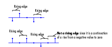
Clk or Rst input does one of the following:
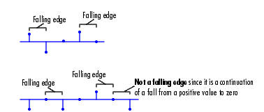
Clk or Rst input is a Rising edge or Falling edge (as described above).
Clk or Rst input is not zero.
Clk port, and enables the Samples per output frame and Sample time parameters. The block increments or decrements the counter at a constant interval, Ts, specified by the Sample time parameter (for more information, see Free-Running Operation below). The Rst port behaves as if the Count event parameter were set to Non-zero sample.
Note
When running simulations in the Simulink MultiTasking mode, sample-based reset and clock signals have a one-sample latency, and frame-based reset and clock signals have one frame of latency. Thus, there is a one-sample or one-frame delay between the time the block detects a trigger event at the Clk or Rst port, and when it applies the trigger. For more information on latency and the Simulink tasking modes, see Excess Algorithmic Delay (Tasking Latency) and the topic on the Simulation Parameters dialog box in the Simulink documentation.
|
Setting the Counter Size and Initial Count Parameters
At the start of the simulation, the block sets the counter to the value specified by the Initial count parameter, which can be any integer in the range defined by the Counter size parameter. The Counter size parameter allows you to choose from three standard counter ranges, or to specify an arbitrary counter limit:
Sample-Based Operation
The block operates in sample-based mode when the Clk input is a sample-based scalar. Sample-based vectors and matrices are not accepted.
When the Count direction parameter is set to Up, a sample-based trigger event at the Clk input causes the block to increment the counter by one. The block continues incrementing the counter when triggered until the counter value reaches the upper count limit (e.g., 255 for an 8-bit counter). At the next Clk trigger event, the block resets the counter to 0, and resumes incrementing the counter with the subsequent Clk trigger event.
When the Count direction parameter is set to Down, a sample-based trigger event at the Clk input causes the block to decrement the counter by one. The block continues decrementing the counter when triggered until the counter value reaches 0. At the next Clk trigger event, the block resets the counter to the upper count limit (e.g., 255 for an 8-bit counter), and resumes decrementing the counter with the subsequent Clk trigger event.
Between triggering events the block holds the output at its most recent value. The block resets the counter to its initial state when the trigger event specified in the Count event menu is received at the optional Rst input. When trigger events are received simultaneously at the Clk and Rst ports, the block first resets the counter, and then increments or decrements appropriately. (If you do not need to reset the counter during the simulation, you can disable the Rst port by clearing the Reset input check box.)
The Output pop-up menu provides three options for the output port configuration of the block icon:
Cnt port, which produces the current value of the counter as a sample-based scalar with the same sample period as the inputs.
Hit port. The Hit port produces zeros while the value of the counter does not equal the integer Hit value parameter setting. When the counter value does equal the Hit value setting, the block generates a value of 1 at the Hit port. The output is sample-based with the same sample period as the inputs.
Frame-Based Operation
The block operates in frame-based mode when the Clk input is a frame-based vector (i.e., single channel). Multichannel frame-based inputs are not accepted.
Frame-based operation is the same as sample-based operation, except that the block increments or decrements the counter by the total number of trigger events contained in the Clk input frame. A trigger event that is split across two consecutive frames is counted in the frame that contains the conclusion of the event. When a trigger event is received at the Rst port, the block first resets the counter, and then increments or decrements the counter by the number of trigger events contained in the Clk frame.
The Cnt and Hit outputs are sample-based scalars with sample period equal to the Clk input frame period.
Free-Running Operation
The block operates in free-running mode when Free running is selected from the Count event menu.
The Rst port behaves as if the Count event parameter were set to Non-zero sample (triggers a reset at each sample time that the Rst input is not zero).
The Clk input port is disabled in this mode, and the block simply increments or decrements the counter using the constant sample period specified by the Sample time parameter, Ts. The Cnt output is a frame-based M-by-1 matrix containing the count value at each of M consecutive sample times, where M is specified by the Samples per output frame parameter. The Hit output is a frame-based M-by-1 matrix containing the hit status (0 or 1) at each of those M consecutive sample times. Both outputs have a frame period of M*Ts.
Example
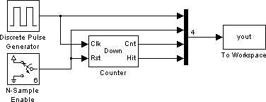
In the model below, the Clk port of the Counter block is driven by the Simulink Pulse Generator block, and the Rst port is triggered by an N-Sample Enable block. All of the Counter block's inputs and outputs are multiplexed into a single To Workspace block using a 4-port Mux block.
To run the model, first select Simulation Parameters from the Simulation menu, and set the Stop time to 30. Then adjust the block parameters as described below. (Use the default settings for the Pulse Generator and To Workspace blocks.)
20
5
4

4.
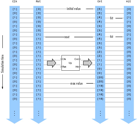
The figure below shows the first 22 samples of the model's four-column output, yout. The first column is the Counter block's Clk input, the second column is the block's Rst input, the third column is the block's Cnt output, and the fourth column is the block's Hit output.
You can see that the seventh input samples to both the Clk and Rst ports of the Counter block represent trigger events (rising edges), so at this time step the block first resets the counter to its initial value of 5, and then immediately decrements the count to 4. When the counter reaches its minimum value of 0, it rolls over to its maximum value of 20 with the following trigger event at the Cnt port.
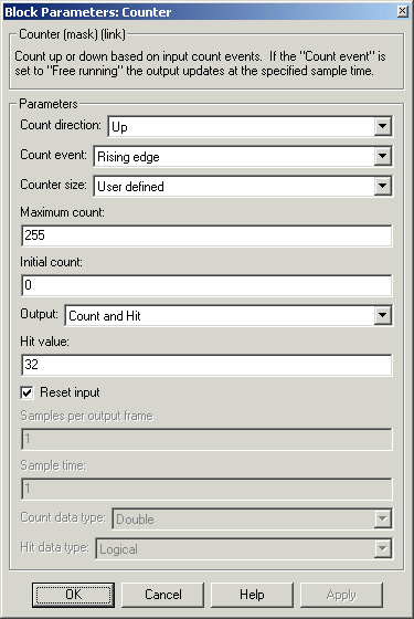
Dialog Box
Clk or Rst ports. Free running disables the Clk port, and counts continuously with the period specified by the Sample time parameter. For more information on all the possible settings, see Setting the Count Event Parameter.Cnt, Hit, or both.1 at the (optional) Hit output. This parameter is available when Hit or Count and Hit are selected in the Output menu. Tunable, except in the Simulink external mode.Rst input port when selected.Cnt output port. This parameter is available when Free running is selected in the Count event menu.Hit output port. For information on the Logical and Boolean options of this parameter, see Effects of Enabling and Disabling Boolean Support. This parameter is available when Free running is selected in the Count event menu and Hit or Count and Hit is selected in the Output menu. Supported Data Types
Rst port. The block may output Boolean values from the Hit output port depending on the Hit data type parameter setting, as described in Effects of Enabling and Disabling Boolean Support. To learn how to disable Boolean output support, see Steps to Disabling Boolean Support.
To learn how to convert to the above data types in MATLAB and Simulink, see Supported Data Types and How to Convert to Them.
See Also
| Edge Detector |
DSP Blockset |
| N-Sample Enable |
DSP Blockset |
| N-Sample Switch |
DSP Blockset |
Also see Switches and Counters for a list of all the blocks in the Switches and Counters library.
| | Correlation | Covariance AR Estimator | |