
| Data Acquisition Toolbox |   |
Quantization
As discussed in the previous section, sampling takes a snapshot of the input signal at an instant of time. When the snapshot is taken, the sampled analog signal must be converted from a voltage value to a binary number that the computer can read. The conversion from an infinitely precise amplitude to a binary number is called quantization.
During quantization, the A/D converter uses a finite number of evenly spaced values to represent the analog signal. The number of different values is determined by the number of bits used for the conversion. Most modern converters use 12 or 16 bits. Typically, the converter selects the digital value that is closest to the actual sampled value.
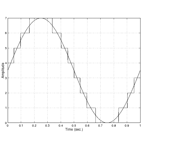
The figure below shows a 1 Hz sine wave quantized by a 3 bit A/D converter.

The number of quantized values is given by 23 = 8, the largest representable value is given by 111 = 22 + 21 + 20 = 7.0, and the smallest representable value is given by 000 = 0.0.
Quantization Error
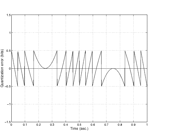
There is always some error associated with the quantization of a continuous signal. Ideally, the maximum quantization error is ±0.5 least significant bits (LSBs), and over the full input range, the average quantization error is zero.
As shown below, the quantization error for the previous sine wave is calculated by subtracting the actual signal from the quantized signal.

Input Range and Polarity
The input range of the analog input subsystem is the span of input values for which a conversion is valid. You can change the input range by selecting a different gain value. For example, National Instruments' AT-MIO-16E-1 board has eight gain values ranging from 0.5 to 100. Many boards include a programmable gain amplifier that allows you to change the device gain through software.
When an input signal exceeds the valid input range of the converter, an overrange condition occurs. In this case, most devices saturate to the largest representable value, and the converted data is almost definitely incorrect. The gain setting affects the precision of your measurement -- the higher (lower) the gain value, the lower (higher) the precision. Refer to How Are Range, Gain, and Measurement Precision Related? for more information about how input range, gain, and precision are related to each other.
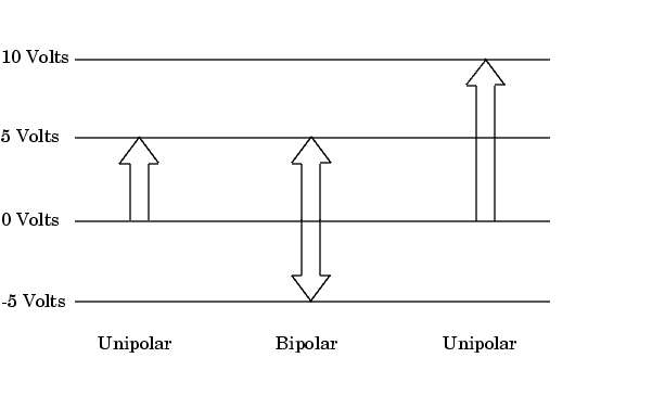
An analog input subsystem can typically convert both unipolar signals and bipolar signals. A unipolar signal contains only positive values and zero, while a bipolar signal contains positive values, negative values, and zero.
Unipolar and bipolar signals are depicted below. Refer to the figure in Quantization for an example of a unipolar signal.

In many cases, the signal polarity is a fixed characteristic of the sensor and you must configure the input range to match this polarity.
As you can see, it is crucial to understand the range of signals expected from your sensor so that you can configure the input range of the analog input subsystem to maximize resolution and minimize the chance of an overrange condition.
How Are Acquired Samples Clocked?
Samples are acquired from an analog input subsystem at a specific rate by a clock. Like any timing system, data acquisition clocks are characterized their resolution and accuracy. Timing resolution is defined as the smallest time interval that you can accurately measure. The timing accuracy is affected by clock jitter. Jitter arises when a clock produces slightly different values for a given time interval.
For any data acquisition system, there are typically three clock sources that you can use: the onboard data acquisition clock, the computer clock, or an external clock. The Data Acquisition Toolbox supports all of these clock sources, depending on the requirements of your hardware.
The Onboard Clock. The onboard clock is typically a timer chip on the hardware board that is programmed to generate a pulse stream at the desired rate. The onboard clock generally has high accuracy and low jitter compared to the computer clock. You should always use the onboard clock when the sampling rate is high, and when you require a fixed time interval between samples. The onboard clock is referred to as the internal clock in this guide.
The Computer Clock. The computer (PC) clock is used for boards that do not possess an onboard clock. The computer clock is less accurate and has more jitter than the onboard clock, and is generally limited to sampling rates below 500 Hz. The computer clock is referred to as the software clock in this guide.
External Clock. An external clock is often used when the sampling rate is low and not constant. For example, an external clock source is often used in automotive applications where samples are acquired as a function of crank angle.
 | Sampling | Channel Configuration |  |