

| Data Acquisition Toolbox | |
Accuracy and Precision
Whenever you acquire measured data, you should make every effort to maximize its accuracy and precision. The quality of your measurement depends on the accuracy and precision of the entire data acquisition system, and can be limited by such factors as board resolution or environmental noise.
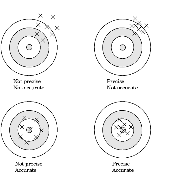
In general terms, the accuracy of a measurement determines how close the measurement comes to the true value. Therefore, it indicates the correctness of the result. The precision of a measurement reflects how exactly the result is determined without reference to what the result means. The relative precision indicates the uncertainty in a measurement as a fraction of the result.
For example, suppose you measure a table top with a meter stick and find its length to be 1.502 meters. This number indicates that the meter stick (and your eyes) can resolve distances down to at least a millimeter. Under most circumstances, this is considered to be a fairly precise measurement with a relative precision of around 1/1500. However, suppose you perform the measurement again and obtain a result of 1.510 meters. After careful consideration, you discover that your initial technique for reading the meter stick was faulty because you did not read it from directly above. Therefore, the first measurement was not accurate.
Precision and accuracy are illustrated below.
For analog input subsystems, accuracy is usually limited by calibration errors while precision is usually limited by the A/D converter. Accuracy and precision are discussed in more detail below.
Accuracy
Accuracy is defined as the agreement between a measured quantity and the true value of that quantity. Every component that appears in the analog signal path affects system accuracy and performance. The overall system accuracy is given by the component with the worst accuracy.
For data acquisition hardware, accuracy is often expressed as a percent or a fraction of the least significant bit (LSB). Under ideal circumstances, board accuracy is typically ±0.5 LSB. Therefore, a 12 bit converter has only 11 usable bits.
Many boards include a programmable gain amplifier, which is located just before the converter input. To prevent system accuracy from being degraded, the accuracy and linearity of the gain must be better than that of the A/D converter. The specified accuracy of a board is also affected by the sampling rate and the settling time of the amplifier. The settling time is defined as the time required for the instrumentation amplifier to settle to a specified accuracy. To maintain full accuracy, the amplifier output must settle to a level given by the magnitude of 0.5 LSB before the next conversion, and is on the order of several tenths of a millisecond for most boards.
Settling time is a function of sampling rate and gain value. High rate, high gain configurations require longer settling times while low rate, low gain configurations require shorter settling times.
Precision
The number of bits used to represent an analog signal determines the precision (resolution) of the device. The more bits provided by your board, the more precise your measurement will be. A high precision, high resolution device divides the input range into more divisions thereby allowing a smaller detectable voltage value. A low precision, low resolution device divides the input range into fewer divisions thereby increasing the detectable voltage value.
The overall precision of your data acquisition system is usually determined by the A/D converter, and is specified by the number of bits used to represent the analog signal. Most boards use 12 or 16 bits. The precision of your measurement is given by

The precision in volts is given by

For example, if you are using a 12 bit A/D converter configured for a 10 volt range, then
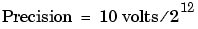
This means that the converter can detect voltage differences at the level of 0.00244 volts (2.44 mV).
How Are Range, Gain, and Measurement Precision Related?
When you configure the input range and gain of your analog input subsystem, the end result should maximize the measurement resolution and minimize the chance of an overrange condition. The actual input range is given by the formula
The relationship between gain, actual input range, and precision for a unipolar and bipolar signal having an input range of 10 V is shown below.
As shown in the table, the gain affects the precision of your measurement. If you select a gain that decreases the actual input range, then the precision increases. Conversely, if you select a gain that increases the actual input range, then the precision decreases. This is because the actual input range varies but the number of bits used by the A/D converter remains fixed.
| Note With the Data Acquisition Toolbox, you do not have to specify the range and gain. Instead, you simply specify the actual input range desired. |
| | Making Quality Measurements | Noise | |