
| Data Acquisition Toolbox |   |
Sampling
Sampling takes a snapshot of the sensor signal at discrete times. For most applications, the time interval between samples is kept constant (for example, sample every millisecond) unless externally clocked.
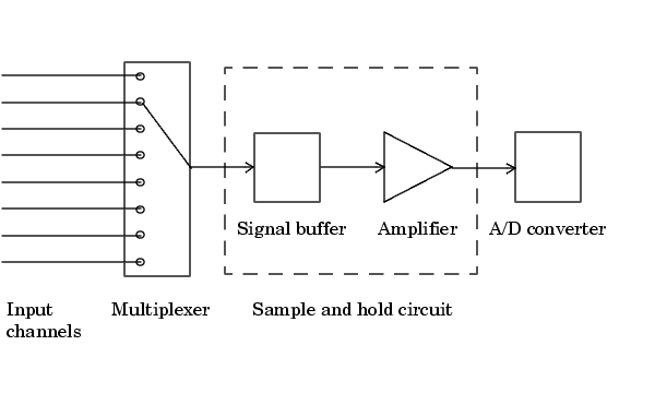
For most digital converters, sampling is performed by a sample and hold (S/H) circuit. An S/H circuit usually consists of a signal buffer followed by an electronic switch connected to a capacitor. The operation of an S/H circuit follows these steps:
A multiplexer, S/H circuit, and A/D converter are illustrated in the next section.
Hardware can be divided into two main categories based on how signals are sampled: scanning hardware, which samples input signals sequentially, and simultaneous sample and hold (SS/H) hardware, which samples all signals at the same time. These two types of hardware are discussed below.
Scanning Hardware
Scanning hardware samples a single input signal, converts that signal to a digital value, and then repeats the process for every input channel used. In other words, each input channel is sampled sequentially. A scan occurs when each input in a group is sampled once.
As shown below, most data acquisition devices have one A/D converter that is multiplexed to multiple input channels.

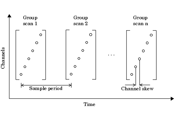
Therefore, if you use multiple channels, those channels cannot be sampled simultaneously and a time gap exists between consecutive sampled channels. This time gap is called the channel skew. You can think of the channel skew as the time it takes the analog input subsystem to sample a single channel.
Additionally, the maximum sampling rate your hardware is rated at typically applies for one channel. Therefore, the maximum sampling rate per channel is given by the formula

Typically, you can achieve this maximum rate only under ideal conditions. In practice, the sampling rate depends on several characteristics of the analog input subsystem including the settling time and the gain, as well as the channel skew. The sample period and channel skew for a multichannel configuration using scanning hardware is shown below.

If you cannot tolerate channel skew in your application, you must use hardware that allows simultaneous sampling of all channels. Simultaneous sample and hold hardware is discussed in the next section.
Simultaneous Sample and Hold Hardware
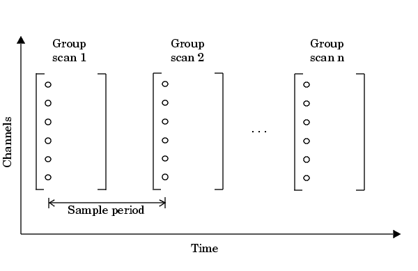
Simultaneous sample and hold (SS/H) hardware samples all input signals at the same time and holds the values until the A/D converter digitizes all the signals. For high-end systems, there can be a separate A/D converter for each input channel.
For example, suppose you need to simultaneously measure the acceleration of multiple accelerometers to determine the vibration of some device under test. To do this, you must use SS/H hardware because it does not have a channel skew. In general, you might need to use SS/H hardware if your sensor signal changes significantly in a time that is less than the channel skew, or if you need to use a transfer function or perform a frequency domain correlation.
The sample period for a multichannel configuration using SS/H hardware is shown below. Note that there is no channel skew.

 | The Analog Input Subsystem | Quantization |  |