 After some time making only low-power
tests and theoretical studies with Tesla coils and similar
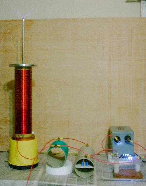
circuits, I started to set up a full-power system. My coil uses a
direct coupling instead of a transformer, as shown in the drawing
below:
After some time making only low-power
tests and theoretical studies with Tesla coils and similar
circuits, I started to set up a full-power system. My coil uses a
direct coupling instead of a transformer, as shown in the drawing
below:A transformerless Tesla coil
(or a 4th-order transformerless multiple resonance network with distributed load capacitance)
After some time making only low-power
tests and theoretical studies with Tesla coils and similar
circuits, I started to set up a full-power system. My coil uses a
direct coupling instead of a transformer, as shown in the drawing
below:
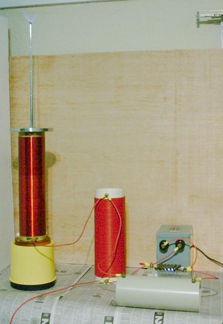
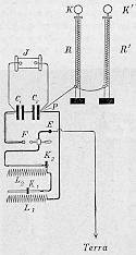
This kind of circuit operates as a Tesla coil does, but without the transformer. It is similar to the resonant system studied by Seibt [18], that produced similar effects on insulated resonant coils., with this connection [1]. The direct coupling restricts a bit the possibilities of the design, since the voltage gain and the number of cycles for energy transfer are directly related. In a conventional Tesla coil with magnetic coupling both can be chosen independently.
The circuit works well, producing ~5 cm streamers around the terminal and hot violet arcs with ~10 cm to a grounded object. It's not a high-power system, but a good test for the concept.
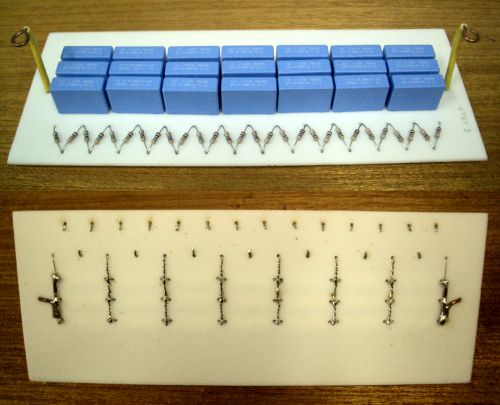
C1 is an 1 nF "MMC" capacitor made with 10 10 nF 1000 V capacitors (Siemens) in series shunted by 2 10 MOhms resistors each. The capacitance is quite small because I want to try to power the system from an electrostatic machine too. The capacitors and resistors were mounted on an acrylic plate, and the plate was inserted in a PVC tube, that serves as support, insulation, support for the terminals, and protection.
L1 is an air core inductor made with #18
solid insulated wire over a 10 cm PVC tube, designed for 314 µH
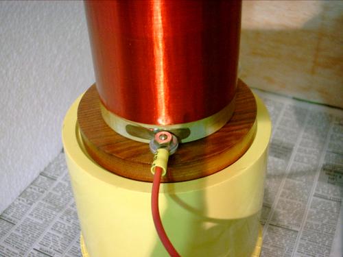
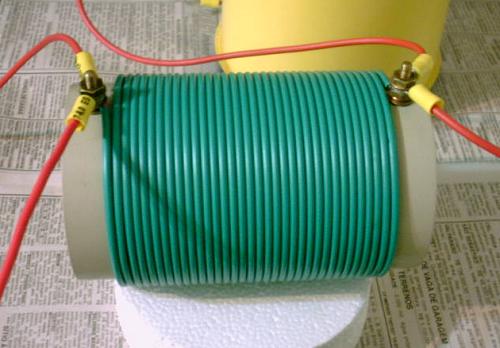
of inductance. L2 is a long coil with 28.2 mH
of inductance, made with 1152 turns of #32 wire around an 8.8 cm
PVC tube. Supported over a plastic box, since the bottom is
"alive" too. I made this inductor using wire taken from
discarded relays, splicing with careful soldering as needed. The
coil was then covered with several layers of polyurethane
varnish. The wire ends in two brass plates glued at the ends of
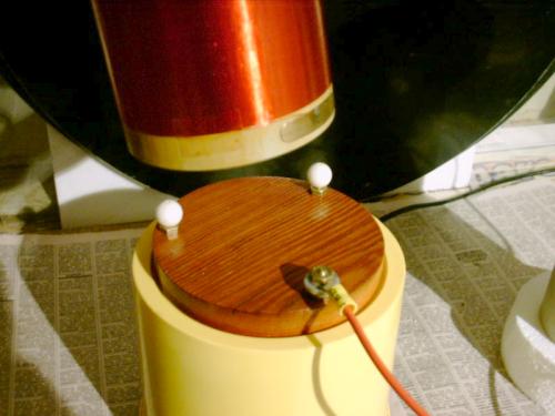
the coil, and the connections are made to these plates. The lower connection is through a metal disk
that presses against the lower plate, while two plastic beads
press against the form at the other side. The form can just be
twisted over the wood base for a firm connection or to be removed. At the top, the terminal has a
plastic disk fixed below it, that fits inside the coil form, and
fixes a copper strip that makes contact with the upper plate.
The terminal plus the secondary coil should have a distributed
capacitance C2 of 11 pF. The coil alone has
5.6 pF. I used as terminal a rounded disk made with aluminum
plate, that serves mainly as a shield to protect the top of the
coil from sparks, with a telescopic antenna mounted over it, that
serves as streamer terminal and allows easy tuning.
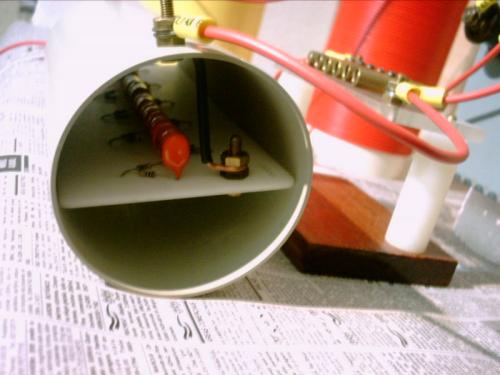
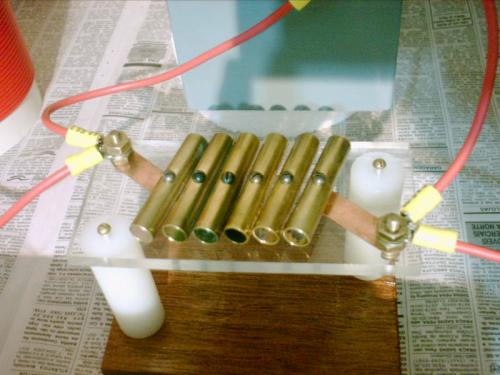
The spark gap was made with 6 brass tubes screwed to an acrylic plate through their centers, so I can adjust the 5 gaps in series precisely by turning the tubes around their centers. It needs a blower to remain cool. It would surely melt the base if operated without one for more than a few seconds. Makes a lot of noise, and the brass tubes turn first to pink and then to black where the sparks form. The ground connection in the tests was just a long wire connected to a metal bucket. The circuit is powered by a NST (neon sign transformer) that produces a single, floating, 5 kV, 30 mA, output, and so can be operated with one side grounded (but the degree of insulation to the case appears to be different in the two terminals. The case sparks to the ground if I reverse the connection shown).. I didn't use filters or safety gaps, since the power is relatively small.
The system was designed using my "multiple resonance" theory (see the references here). It operates in the optimal mode 9:10, oscillating at 270 kHz and 300 kHz during the energy transfer, that takes 5 cycles of 285 kHz. The maximum voltage gain is 9.53. Low-power tests indicate that the system behaves as predicted, producing almost perfect ideal waveforms. The system was tuned by adjusting the length of the telescopic antenna. In the low-power tests and in the power tests, the best length was about 45 cm.
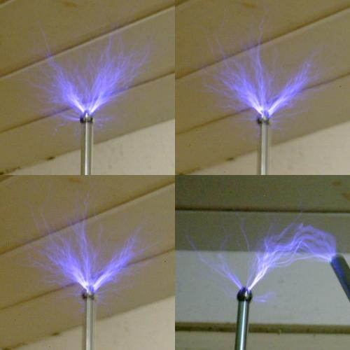
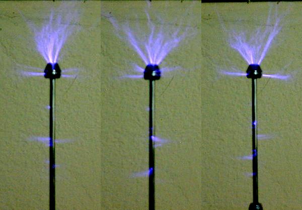
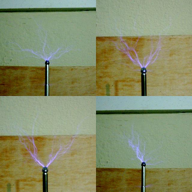
Streamers, or RF corona, that
occasionally develops long branches, with only the thicker tubes
of the antenna extended. An arc to an insulated metal tube is
also shown.
Streamers, with the thinner tube
extended. Little corona plumes form over it too.
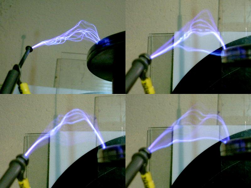
Arcs from the terminal disk to the
ground terminal (the system is not grounded in this test), held
at the end of an insulating bar with a screw. These arcs are very
different from the sparks from an electrostatic machine, being
less irregular.
The system lights fluorescent lamps at some distance away, and
causes strong electromagnetic interference while in operation.
The arcs are not safe to touch. Their current is high due to the
relatively low voltage gain, and they are hot enough to cause
burns. It's possible to draw arcs to a metal rod firmly held in a
hand, apparently without bad efects, feeling only a light
electric shock. This is however, a dangerous procedure.
Design:
This system can be designed in the following way: Select first the operating mode, by choosing two integers k and l with odd difference, that set the ratio of the two oscillation frequencies of the system. A difference of 1 results in higher gain, and values between 5:6 and 25:26 are recommended. The formulas for the component values of a normalized system that oscillates at k and l rad/s and has C2=1 are:
C2
= 1
L2
= 2/(k2+l2)
C1
= ((k2+l2)/(l2-k2))2
L1
= (l2-k2)2/(2(k2+l2)k2l2)
The voltage gain is Av = (k2+l2)/(l2-k2)
To obtain the final required values, it's possible to start from a measured secondary coil L2final and an available C1final, since these are more difficult to adjust, and compute L1final and C2final keeping the same ratios:
L1final =
L1L2final/L2
C2final
= C2C1final/C1
In my example, starting from k=9, l=10, L2final=28.2 mH, and C1final=1 nF, the results are:
Normalized circuit:
C2 = 1 F
L2 = 1.1049723x10⁻² H
C1 = 90.750693 F
L1 = 1.2311575x10⁻⁴ H
Final circuit:
C2final = 11.02 pF
L2final = 28.2 mH
C1final = 1 nF
L1final =314.2 µH
C2 can be adjusted by the size of the terminal. The system oscillates at kf0 and lf0, where:
f0 = (1/(2p))(L2C1/(L2finalC1final))1/2 = 30.0 kHz.
And so, kf0 = 270 kHz and lf0 = 300 kHz. Total energy transfer occurs in 1/(2f0) = 16.7 µs. Note that the really important design equations, ignoring the perfect energy transfer condition, are:
L1C1
= (L1+L2)C2
Av = (C1/C2)1/2
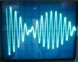
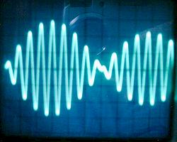
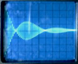
Voltage waveforms:
Below are shown the voltage waveforms observed over C1 and C2, in a low-power test, with the power supply and the spark gap replaced by a low-impedance square-wave generator. VC1 (left) was measured directly, and VC2 (right) by placing the oscilloscope probe close to the terminal, without touching it. 5 cycles or VC1 are required for complete energy transfer, showing that the system is operating very close to mode 9:10.
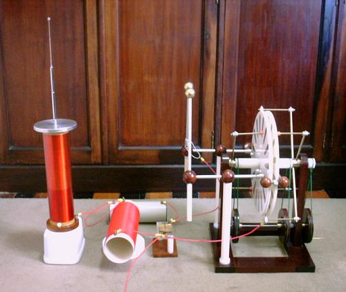
The system can be powered by an electrostatic machine. In the test setup, a triplex Wimshurst machine was used, with the machine output taken between one terminal and the grounded neutralizer circuit. The machine can easily produce 50 µA in this condition, what is enough to charge the 1 nF primary capacitor to 10000 V 5 times per second . Each spark at the gap produces a corona burst at the terminal antenna, or sparks with a few cm of length to a nearby object. With so small input power (250 mW), the output is barely visible, but is clearly audible. For this kind of operation, it would be more efficient to use the high voltage capability of the electrostatic machine to charge a smaller input capacitor to higher voltage. Assuming a constant charging current I, the average input power is found as P=VI/2, where V is the gap voltage.With C1=100 pF charged to 50 kV by 50 µA, and operation in mode 3-4 (L1 = 2.4 mH and voltage gain of 3.6), the machine could charge the capacitor 10 times per second, the input power would climb to 1.25 W and the output voltage could go to 350 kV, with a proper terminal.
Increasing the power:
I made a larger C1, nominally with 5.14 nF, composed of 21 12 nF 1600 V capacitors in a 7 in series, 3 in parallel, array. Each parallel group shunted by 4 10 MOhms resistors in series for voltage equalization in slow charging. It was assembled in the same way, in an acrylic plate inserted in a PVC tube where the terminals are mounted. Its measured capacitance is 5.09 nF. With the same secondary resonator, it's possible to make the circuit operate in mode 21:22, with the elements:
C2 = 11.0 pF
L2 = 28.2 mH
C1 = 5.09 nF
L1 = 61.07 µH
The new primary inductor L1 was made with 34 turns of #18 insulated wire over an 8.8 cm PVC tube, resulting in an inductance of 60.0 µH. The maximum voltage gain reaches 21.5, but the energy transfer time is about twice longer than in the first circuit, and the losses are higher. The circuit works correctly, producing waveforms close to the expected (energy transfer in 37.6 µs, after 11 full cycles of the voltage over C1) producing streamers with up to 12 cm at the antenna, that reach 20 cm or more with a half sphere covering the top of the antenna to avoid premature breakout. The voltage is clearly higher, as can be noticed by the corona over the thick tubes of the antenna, but the streamers look dimmer than in the previous circuit. The input power is about 5 times higher. The streamer length appears to be proportional to the square root of the input power, as usually happens in Tesla coils.
See also a modification of this system, as a "capacitive transformer" Tesla coil, and a program that can compute the required element values for the system..
Continuation:
Faster energy transfer still without a transformer is possible with an upgrade to a 6th-order system, with an additional LC circuit before the resonator, forming a kind of directly coupled magnifier. A system using a transformer, in the classical Tesla coil configuration, also results in significant improvement.
Warning:
This device is powered by a power source that has enough voltage, and specially enough current, to give a fatal shock. The NST, the terminals of C1, L1, and the spark gap must not be touched in any circunstance while the system is energized.
Created: 27 July 2002
Last update: 26 August 2006
Created and maintained by Antonio Carlos
M. de Queiroz
See also: Electrostatic Machines