A "Triplex" Wimshurst Machine
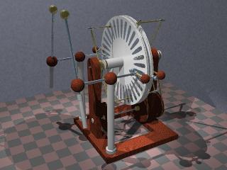 The "triplex" Wimshurst electrostatic
machine [5] is basically a Wimshurst machine with three disks. The
two outer disks turn in one direction, and the central disk turn
in the other direction. Neutralizing bars cross the two outer
disks in parallel and another neutralizer, with opposite
inclination, touches the sectors of the central disk. The output
is taken from the three disks at the horizontal diameter. The
central disk has its sectors mounted between two insulating
disks.For simplicity of construction the central disk can be made
as two conventional Wimshurst disks placed at small distance. The
machine built in this way is then just a pair of Wimshurst
machines operating side-by-side, at small distance, and
interconnected in parallel.
The "triplex" Wimshurst electrostatic
machine [5] is basically a Wimshurst machine with three disks. The
two outer disks turn in one direction, and the central disk turn
in the other direction. Neutralizing bars cross the two outer
disks in parallel and another neutralizer, with opposite
inclination, touches the sectors of the central disk. The output
is taken from the three disks at the horizontal diameter. The
central disk has its sectors mounted between two insulating
disks.For simplicity of construction the central disk can be made
as two conventional Wimshurst disks placed at small distance. The
machine built in this way is then just a pair of Wimshurst
machines operating side-by-side, at small distance, and
interconnected in parallel.
The machine can be built with a central disk with embedded
sectors accessed through the edge, as in this
highly efficient machine [46], designed
by H. Wommelsdorf in the early 1900's, but the construction with
two central disks allows the construction of a sectorless
machine, as this, built by S. Klein by
2000.
The interaction between the electric
fields around the two disk pairs allows a greater charge
density in the surface of the central disks than would be
possible in a single machine. The result is that the triplex
machine produces three or four times more current than a single
Wimshurst machine with the same disks and speed, while two
separate machines at most double the current.
Construction
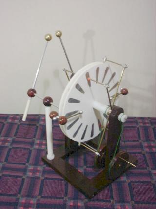
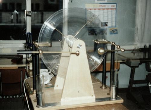
In the first months of 2000 I made one of these machines,
reusing some of the materials from a dismantled symmetrical Toepler machine. The machine has four
identical white acrylic disks with 2.5 mm of thickness and 36.5
cm of diameter. The two outer disks were mounted with screws on
nylon bosses with pulleys, that turn on pairs of ball bearings
over a central steel axle. The two central disks were mounted on
a short brass cylinder, that was fixed to the axle by a set
screw. The axle turns on ball bearings mounted in the upright
wood supports. Three pulleys were mounted in another axle below
the disks, supported by nylon bushings in the upright supports,
and turn the two outer disks in one direction, and the upper axle
with the two central disks in the other direction, through a
crossed cord in the pulley that also serves as crank, at the
outer side of the upright supports. The disks turn all at the
same speed. The cords were made of leather. The lower pulleys
were made in wood, with central brass cylinders, and fixed to the
lower axle by set screws. The speed multiplication in the pulley
system is of 4:1.
The disks were sectored with 32 sectors in each disk, each
sector 7.5 cm long, with maximum width of 2 cm, keeping constant
distance along the radius of the disks. One pair of disks was
sectored with adhesive aluminum foil, and other with foil taken
from discardable pizza pans glued with contact glue. I wanted to
see if the two materials show some difference in performance (no
difference was observed).
The neutralizers were mounted on brass rings that can be
rotated over brass pieces screwed to the upright supports, that
also fix in place the ball bearings that support the upper axle.
Set screws at low pressure allow easy positioning of the
neutralizers at any angle. The neutralizers were made of brass
bars screwed in the rings, that support other bars fixed to them
by aluminum cylinders with screws. The neutralizer brushes for
the outer disks were made of thin nickel-chrome wire fixed in
place by plastic beads. The brushes for the central neutralizers
are double, and mounted on additional thin brass bars fixed to
the horizontal sections of the bars by aluminum blocks with
screws. The central brushes were made of brushes of fibrous
material taken from the output slot of a discarded laser printer.
Wire brushes there would be too short and break easily. Small
plastic beads were placed at the ends of the central neutralizer
bars. The central collectors can be rotated to experiment the
idea that more output current can be obtained with the charge
collectors displaced in the direction of the adjacent
neutralizers [5] (works) or even
removed, what should keep practically the same output current (it
drops a bit).
The charge collectors were made of brass bars interconnected
by wood balls and a short brass rod, and terminated in aluminum
balls at the outer sides and by small plastic beads at the inner
sides. The central charge collectors were mounted in aluminum
balls that slide over the rods that interconnect the outer
collectors, fixed in place by manual screws with aluminum ball
heads. The collectors have brushes of the same fibrous material
used in the central neutralizers, ending close to the disk
surfaces, instead of points. They appear to work as well as metal
points, and there is no risk of scratching the disks in
accidental touchings. I used four brushes in each bar.
The charge collector assemblies are fixed by aluminum blocks
with manual screws to aluminum tube conductors. The conductors
cross and are supported by wood balls mounted over long
insulators made of PVC tubes closed at both ends with nylon
blocks. The lower blocks serve as base for the columns, and the
upper blocks insert in holes below the wood balls. Set screws in
the balls fix the conductors in place.
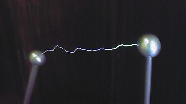
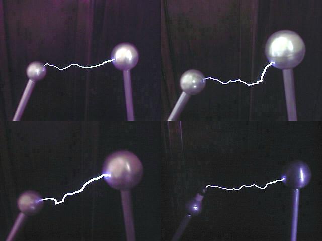
The spark terminals were made with brass balls made by metal spinning, with 3.2 cm of diameter. The
balls are screwed into short brass plugs that slide into long
aluminum tubes. This allows for easy replacement of the balls for
experiments (note the different aluminum balls in some of the
spark images). The tubes cross wood balls and are connected to
slotted brass plugs that insert into the horizontal conductors,
and can be rotated to any position. The insulating handles are
sections of thin PVC tubes, adapted by nylon blocks to the tubes.
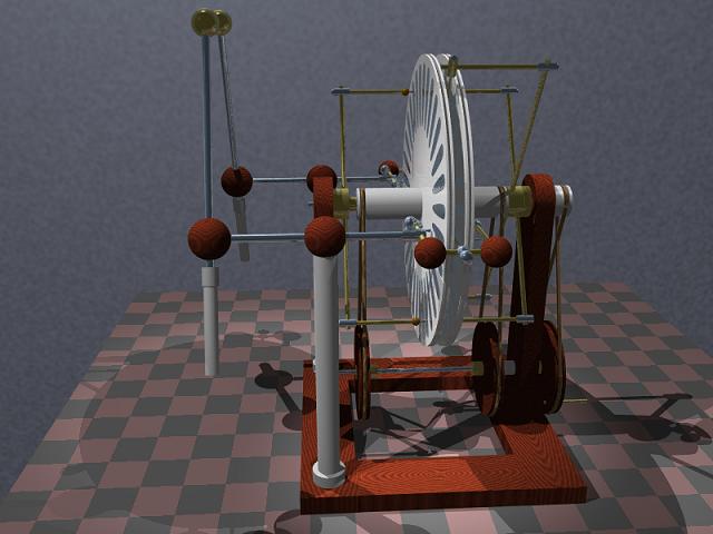
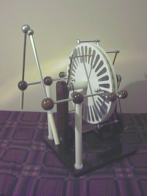
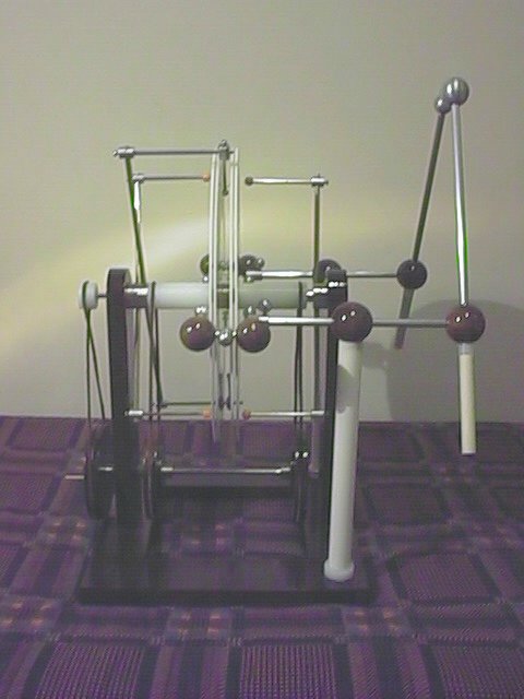
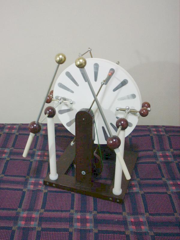
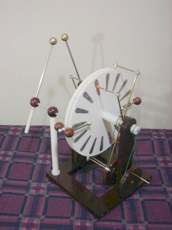
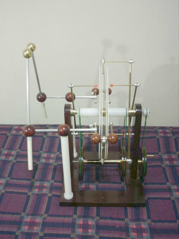
The support structure was made of four wood bars fixed with
screws, and two upright supports fixed to the base by pairs of
screws from below. Front view, back view, and. side
view. of the complete machine.
Performance
The machine self-started easily, and produced a lot of
current. Its output current reached 50 µA at two turns per
second at the crank. This is four times the expected
current for a Wimshurst machine with the same disks and
speed. Really, with one of the lateral disks stopped, the output
current reached about 12 µA only. At the maximum possible crank
speed of 4 turns/second, the machine reached 100 µA. This
current was measured connecting a microamperimeter across the
terminals, through two long wood bars, serving as resistors. The
same current could also be measured between one terminal and the
neutralizers (ground). This last form of measurement keeps one of
the sides of the machine at high voltage.
It was soon evident, however, that the sectors were too close
together, as the machine was easily sparking through the disks,
from one charge collector through a series of sectors to a
neutralizer, and from one of the other neutralizers through
another series of sectors to the other charge collector. Long sparks at the output could only be
obtained with the neutralizers at an almost vertical position. In
a dry day, the machine could produce eventual 15 cm sparks, but
normally not more than 8-12 cm sparks
before sparking through the disks.
 In October 2000, I removed half of the
sectors of the disks, leaving only 16 widely spaced sectors in
each disk. This eliminated the problem of sparking through the
disks completely. The machine then produced consistently sparks
with up to 15 cm with its normal terminal balls and neutralizers
at little more than 60 degrees with the horizontal. Attempts to
produce longer sparks result in sparking through the center of
the machine, directly between the charge collectors. The output
short-circuit current dropped to one half of what it was (25 µA
at 2 turns/s at the crank), but the current measured in
high-voltage conditions, from one terminal to the neutralizers,
reached 35 uA at the same conditions. This indicates that at low
output voltage the charges are transported in the sectors, but at
higher voltages some of the area around the sectors is also
effectively used. A dislocation of the central charge collectors
in the direction of the adjacent neutralizers, of just 2-3 cm,
increases the output current back to the original level, at the
expense of a small decrease in the maximum spark length.
In October 2000, I removed half of the
sectors of the disks, leaving only 16 widely spaced sectors in
each disk. This eliminated the problem of sparking through the
disks completely. The machine then produced consistently sparks
with up to 15 cm with its normal terminal balls and neutralizers
at little more than 60 degrees with the horizontal. Attempts to
produce longer sparks result in sparking through the center of
the machine, directly between the charge collectors. The output
short-circuit current dropped to one half of what it was (25 µA
at 2 turns/s at the crank), but the current measured in
high-voltage conditions, from one terminal to the neutralizers,
reached 35 uA at the same conditions. This indicates that at low
output voltage the charges are transported in the sectors, but at
higher voltages some of the area around the sectors is also
effectively used. A dislocation of the central charge collectors
in the direction of the adjacent neutralizers, of just 2-3 cm,
increases the output current back to the original level, at the
expense of a small decrease in the maximum spark length.
In May 2002, I replaced the leather cords (shoe strings) by 3
mm polyurethane cords, to solve a constant problem with the cords
becoming loose or breaking. The crossed cord driving the central
disks, in particular, was problematic because the tension on it
is at least twice higher than in the other two, and this machine
is hard to crank when charged.
The replacement solved the problem, but the machine still has
some mechanical problems, that will be solved in a future
rebuilding. The pulleys should be larger, and the support
structure should be stronger for a machine of this size. Also,
the distance between the outer brushes and the disks should be
adjustable, and the charge collectors points could look better.
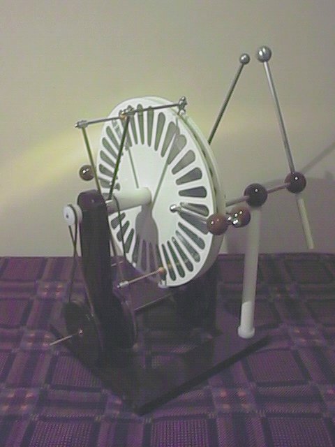
The machine, in front view, back view, and side
view.
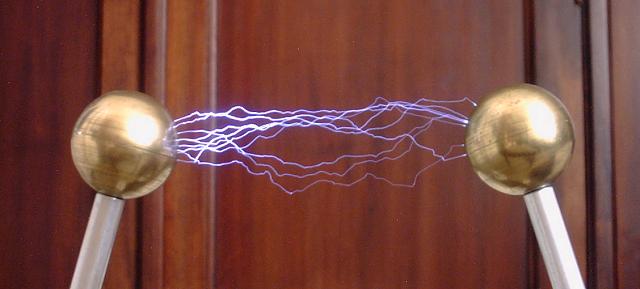
Multiple sparks
Created: 22/10/2000
Last update: 16/2/2003
Developed and maintained by Antonio Carlos
M. de Queiroz
Return to Electrostatic Machines
 The "triplex" Wimshurst electrostatic
machine [5] is basically a Wimshurst machine with three disks. The
two outer disks turn in one direction, and the central disk turn
in the other direction. Neutralizing bars cross the two outer
disks in parallel and another neutralizer, with opposite
inclination, touches the sectors of the central disk. The output
is taken from the three disks at the horizontal diameter. The
central disk has its sectors mounted between two insulating
disks.For simplicity of construction the central disk can be made
as two conventional Wimshurst disks placed at small distance. The
machine built in this way is then just a pair of Wimshurst
machines operating side-by-side, at small distance, and
interconnected in parallel.
The "triplex" Wimshurst electrostatic
machine [5] is basically a Wimshurst machine with three disks. The
two outer disks turn in one direction, and the central disk turn
in the other direction. Neutralizing bars cross the two outer
disks in parallel and another neutralizer, with opposite
inclination, touches the sectors of the central disk. The output
is taken from the three disks at the horizontal diameter. The
central disk has its sectors mounted between two insulating
disks.For simplicity of construction the central disk can be made
as two conventional Wimshurst disks placed at small distance. The
machine built in this way is then just a pair of Wimshurst
machines operating side-by-side, at small distance, and
interconnected in parallel. 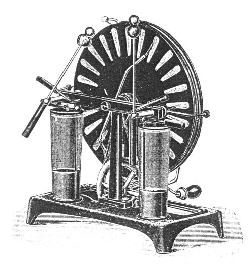