A Capacitive Transformer Tesla coil
(or a 4th-order capacitively coupled
multiple resonance network with distributed capacitances)
 This experimental device is
a 4th-order multiple resonance network where the floating
elements are capacitors and all the inductors are grounded. It
can be interpreted as a kind of Tesla coil where the inductive
transformer is replaced by a "capacitive transformer".
Its schematic diagram is as shown below.
This experimental device is
a 4th-order multiple resonance network where the floating
elements are capacitors and all the inductors are grounded. It
can be interpreted as a kind of Tesla coil where the inductive
transformer is replaced by a "capacitive transformer".
Its schematic diagram is as shown below.
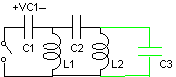
C1 is charged to VC1
and the switch is closed. During the resulting transient, all the
energy that was in C1 is transferred to C3+C2.
C3 would be not necessary for the operation
of the circuit, but its presence is unavoidable and it must be
taken into account. In the actual construction, C3
and C2 are distributed capacitances. C2
is the capacitance between an interrupted metal ring connected to
the lumped L1 and C1,
placed around the inductor L2, and the
combination of L2 and a terminal mounted
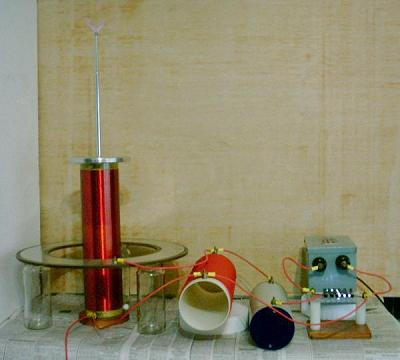
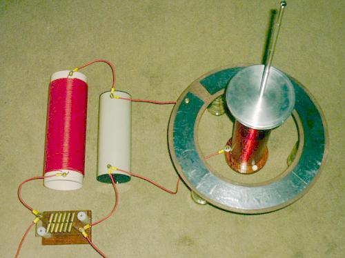
above it. C3 is the remaining of the 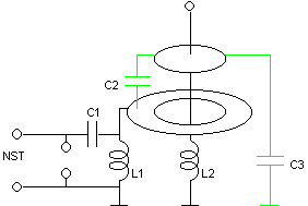 capacitance of the terminal and of L2,
coupled to the ground. The elements used are the same of my
"transformerless Tesla coil".
The connections are as in the figure at the left. The antenna at
the top of the terminal serves as breakout point and for tuning. Another view, in this case with C1
grounded and L1 suspended (a more dangerous
connection, because the NST becomes connected to the influence
ring), that works practically in the same way. Note the
interruption in the ring, to avoid the formation of a shorted
turn around L2. (doesn't make difference,
actually). The "influence ring" was made with a strip
of strong aluminum foil glued to a wooden base.
capacitance of the terminal and of L2,
coupled to the ground. The elements used are the same of my
"transformerless Tesla coil".
The connections are as in the figure at the left. The antenna at
the top of the terminal serves as breakout point and for tuning. Another view, in this case with C1
grounded and L1 suspended (a more dangerous
connection, because the NST becomes connected to the influence
ring), that works practically in the same way. Note the
interruption in the ring, to avoid the formation of a shorted
turn around L2. (doesn't make difference,
actually). The "influence ring" was made with a strip
of strong aluminum foil glued to a wooden base.
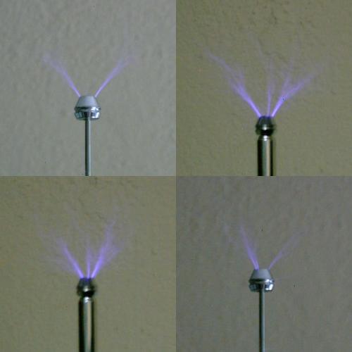
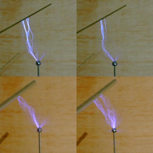
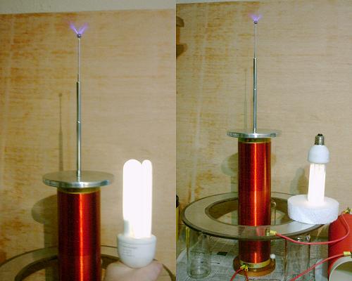
The device produces corona
at the teminal and arcs to insulated
or grounded metal rods placed near the terminal. It also lights fluorescent lamps without contact
easily. The output power is smaller than in the directly coupled system, but not much. A
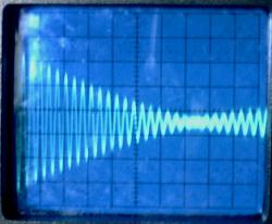
low-power test shows that when optimally tuned the system
operates in the mode 20:21 (voltage over L1),
A model corresponding to this is:
C3 = 6.05 pF
C2 = 5.18 pF
L2 = 28.2 mH
C1 = 1 nF
L1 = 315 µH
The maximum voltage gain would be 9.44. It
oscillates at 276 and 290 kHz and shows complete energy transfer
in 10.5 cycles (36.2 µs) of the voltage in C1.
C3 is 54% of the load capacitance. The
directly coupled system has a maximum gain of 9.53, but it
operates in mode 9:10, with about twice faster energy transfer,
having so better efficiency because with less cycles less energy
is lost before being transferred.
Observe that the "capacitive
transformer" in this circuit is not only capacitive. Its
upper branch is formed by C2, but its lower
branch is formed by C1 in parallel with L1.
The "turns ratio" of this transformer is then:
n = 1+C1/C2-1/(w2C2L1)
Evaluated for w = 2p276x103 and w
= 2p290x103 rads/s,
the frequencies where the whole circuit resonates, the result is
n = –9.46 and n = 9.46 respectively (with exact values used
in the calculations), exactly the actual voltage gain that is
obtained considering initial charge in C1+C2
and final energy in C2+C3,
that is ((C1+C2)/(C2+C3))1/2
= 9.46 (The circuit shown above charges only C1
initially. It would charge C1 and C2
if C1 and L1 are
interchanged, but the difference is insignificant). Note that as
the circuit does not operate in sinusoidal steady state, the use
of the "turns ratio" to predict the gain is only an
approximation, that works in this case as well as it works in a
regular Tesla coil with an inductive transformer.
This circuit has the same restrictions of the
directly coupled system, with the gain being proportional to the
number of cycles required for complete energy transfer, but in
this case the presence of C3 adds another
problem, turning the number of required cycles even larger. The
system can be designed by a method similar to the used for the
directly coupled system, and the design can be extended to
higher-order systems. The ideal tuning relation is:
L1(C1+C2)
= L2(C2+C3)
The system was also run with a lower impedance
primary circuit, with C1 = 5.09 nF and L1
= 60.0 µH, the same elements also used in the improved
version of my directly coupled system.
It can be tuned to the very slow mode 41:42,
with energy transfer in 72.4 µs, 21 cycles, but produces 5 cm
streamers at the antenna instead of the corona of the first
version.
The mreshp
program can calculate the required element values for this
structure, and for many others. A simpler
program is also available.
Warning:
This device is powered by a
power source that has enough voltage, and specially enough
current, to give a fatal shock. The NST, the terminals of C1,
L1,
the induction ring, and the spark gap must not be touched in any
circunstance while the system is energized. L2
and the terminal are also not safe to touch. The current of the
arcs is high enough to cause serious burns.
Created: 14 August 2002
Last update: 07 December 2002
Created and maintained by Antonio Carlos
M. de Queiroz
See also: Electrostatic Machines
