| Virtual Reality Toolbox |
  |
Connecting a Simulink Model to a Virtual World
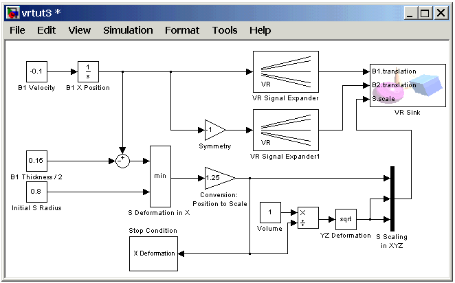
After you create a virtual world, a Simulink model, and add a Virtual Reality Toolbox block to your model, you can define the associations between the model signals and the virtual world. This procedure uses the model vrtut3.mdl as an example. It assumes that you have opened the model and that you have added a VR Sink block. See Adding a Virtual Reality Toolbox Block.
- In the Simulink window, double-click the VR Sink block.
- The Block Parameters: VR Sink dialog box opens again.
- Click Browse.
- The Select World dialog box opens.
- Select
vrtut3.wrl, and then click Open.
- In the tree viewer, select the S scale, B1 translation, and B2 translation check boxes as the nodes you want to connect to your model signals. Click OK to close the dialog box.
- The Virtual Reality Toolbox block appears with corresponding inputs.
- Connect these input lines to the matching signals in the model. These signals were originally connected to Scope blocks.

- Double-click the VR Sink block. In the Block Parameters: VR Sink dialog box, click the View button.
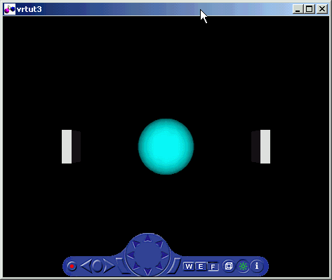
- Your default viewer opens and displays the virtual world. For more information on changing your default viewer, see Setting the Default Viewer of Virtual Scenes.

- In the Simulink window, from the Simulation menu, click Start.
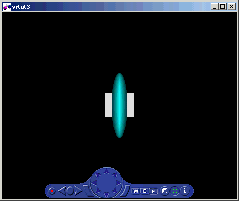
- In your default viewer, you see a 3-D animation of the scene. Using the viewer controls you can observe the action from various viewpoints.
When the width of the sphere is reduced to 0.4 of its original size, the simulation stops running.
This example shows you how to create and use a very simple virtual reality model. Using the same method, you can create more complex models for solving your particular problems.
 | Creating a Box in a Virtual World | | Viewing a Virtual World |  |


