| Virtual Reality Toolbox |
  |
Creating a Box in a Virtual World
- In the tree, click New World (the topmost item). On the toolbar, click the box icon
 .
.
- A new box object appears at the same position as the sphere centered in the origin of the coordinate system. Note that the sphere is hidden behind the box and currently is not visible.
- Double-click the translation field under the Transform node.
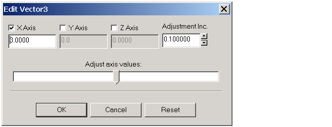
- The Edit Vector 3 dialog box opens. Notice that there are two Transform nodes. Use the one with the Box node in its subtree.
- Select the X Axis check box. In the text box below, enter 3, then click OK.

- The position of the box is set to [3 0 0].
- Expand the Box node. Double-click the size field under the Box node.
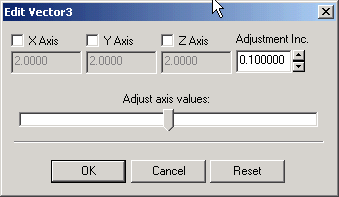
- The Edit Vector 3 dialog box opens.

- Set the values to
[0.3 1 1], and then click OK.
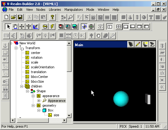
- The figure below shows the tree view with the expanded branch of the box.

- Create a second box the same way you created the first box.
- To move the second box to its correct place, double-click the translation field of the second Transform node, and change its position to
[-3 0 0].
- Double-click the size field under the Box node. Set the values to
[0.3 1 1], and then click OK.
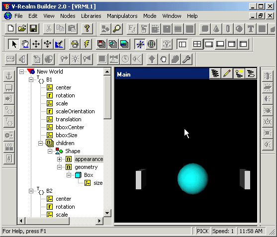
- The scene is now complete.
- To access the positions of the boxes from a Virtual Reality Toolbox block, give each Transform node a name. For example, set the name of the first Transform node to
B1 and the second Transform node to B2. The Virtual Reality Toolbox allows you to access fields of only those nodes that are named in virtual worlds.
- Save the virtual world as
vrtut3.wrl in the same working directory where the file vrtut3.mdl resides, and then exit V-Realm Builder.
| Caution
If you want to use your virtual worlds with the Virtual Reality Toolbox, do not save them in a compressed Gzip format.
|
Your next task is to connect the model outputs to the Virtual Reality Toolbox block in your Simulink model. See Connecting a Simulink Model to a Virtual World.
 | Creating a Sphere in a Virtual World | | Connecting a Simulink Model to a Virtual World |  |


