
| Real-Time Workshop |   |
External Signal & Triggering Dialog Box
Clicking the Signal & triggering button activates the External Signal & Triggering dialog box.

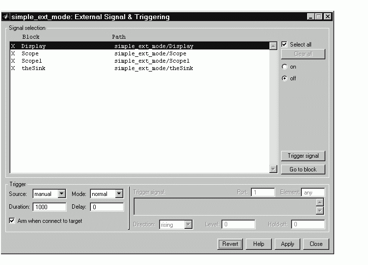
Figure 6-7: Default Settings of the External Signal & Triggering Dialog Box
The External Signal & Triggering dialog box displays a list of all blocks and subsystems in your model that support external mode signal uploading. See External Mode Compatible Blocks and Subsystems for information on which types of blocks are external mode compatible.
The External Signal & Triggering dialog box lets you select which signals are collected from the target system and viewed in external mode. It also lets you select a signal that triggers uploading of data when certain signal conditions are met, and define the triggering conditions.
Default Operation
Figure 6-7 shows the default settings of the External Signal and Triggering dialog box. The default operation of the External Signal and Triggering dialog box is designed to simplify monitoring the target program. If you use the default settings, you do not need to preconfigure signals and triggers. Simply start the target program and connect the Simulink model to it. All external mode compatible blocks will be selected and the trigger will be armed. Signal uploading will begin immediately upon connection to the target program.
Signal Selection
All external mode compatible blocks in your model appear in the Signal selection list of the External Signal & Triggering dialog box. You use this list to select signals to be viewed. An X appears to the left of each selected block's name.
The Select all check box selects all signals. By default, Select all is on.
If Select all is off, you can select or deselect individual signals using the on and off radio buttons. To select a signal, click on the desired list entry and click the on radio button. To deselect a signal, click on the desired list entry and click the off radio button. Alternatively, you can double-click a signal in the list to toggle between selection and deselection.
The Clear all button deselects all signals.
Trigger Options
The Trigger panel located at the bottom left of the External Signal & Triggering dialog box contains options that control when and how signal data is collected (uploaded) from the target system. These options are:
manual or signal. Selecting manual directs external mode to start logging data when the Arm trigger button on the External Mode Control Panel is clicked.
signal tells external mode to start logging data when a selected trigger signal satisfies trigger conditions specified in the Trigger signal panel. When the trigger conditions are satisfied (that is, the signal crosses the trigger level in the specified direction) a trigger event occurs. If the trigger is armed, external mode monitors for the occurrence of a trigger event. When a trigger event occurs, data logging begins.
manual, uploading begins immediately. If the trigger mode is signal, monitoring of the trigger signal begins immediately, and uploading begins upon the occurrence of a trigger event.
normal or one-shot. In normal mode, external mode automatically rearms the trigger after each trigger event. In one-shot mode, external mode collects only one buffer of data each time you arm the trigger. See Data Archiving Dialog Box for further details on the effect of the Mode setting.
Trigger Signal Selection
You can designate one signal as a trigger signal. To select a trigger signal, select signal from the Trigger Source menu. This activates the Trigger signal panel (see Figure 6-8). Then, click on the desired entry in the Signal selection list, and click the Trigger signal button.
When a signal is selected as a trigger, a T appears to the left of the block's name in the Signal selection list. In Figure 6-8, the Pilot G force Scope signal is the trigger. Pilot G force Scope is also selected for viewing, as indicated by the X to the left of the block name.
Figure 6-8: Signals & Triggering Window with Trigger Selected
After selecting the trigger signal, you can define the trigger conditions in the Trigger signal panel, and set the Port and Element fields located on the right side of the Trigger panel.
Setting Trigger Conditions
Note
The Trigger signal panel and the Port and Element fields of the External Signal & Trigger dialog box are enabled only when Trigger source is set to signal.
|
By default, any element of the first input port of the specified trigger block can cause the trigger to fire (i.e., Port 1, any element). You can modify this behavior by adjusting the Port and Element fields located on the right side of the Trigger panel. The Port field accepts a number or the keyword last. The Element field accepts a number or the keywords any and last.
The Trigger Signal panel defines the conditions under which a trigger event will occur. These are:
rising, falling, or either. This specifies the direction in which the signal must be travelling when it crosses the threshold value. The default is rising.
normal mode. Expressed in base rate steps, Hold-off is the time between the termination of one trigger event and the rearming of the trigger.
 | Target Interface Dialog Box | Data Archiving Dialog Box |  |