| SimPowerSystems |
  |
Session 3: Simulating Transients
In this session you
- Learn how to create an electrical subsystem
- Simulate transients with a circuit breaker
- Compare time domain simulation results with different line models
- Learn how to discretize a circuit and compare results obtained with continuous variable time-step algorithm and discrete system
One of the main uses of the Power System Blockset is to simulate transients in electrical circuits. This can be done with either mechanical switches (circuit breakers) or switches using power electronic devices.
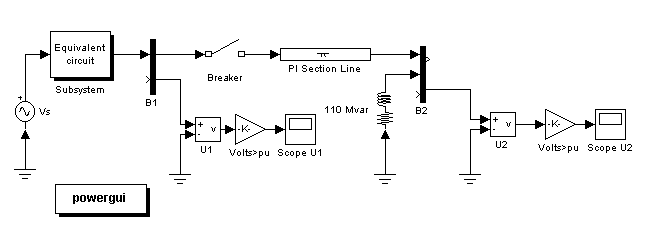
First open your circuit1 system and delete the current source connected at bus B2. Save this new system as circuit2. Before connecting a circuit breaker, you need to modify the schematic diagram of circuit2. As with Simulink, the Power System Blockset allows you to group several components into a subsystem. This feature is useful to simplify complex schematic diagrams.
Use this feature to transform the source impedance into a subsystem by
- Selecting the two blocks identified as Rs_eq and Z_eq by surrounding them with a bounding box (left mouse button) and using the Edit --> Create subsystem menu item. The two blocks now form a new block called Subsystem.

- Using the Edit --> Mask subsystem menu item, change the icon of that subsystem. In the Icon section of the mask editor, enter the following drawing command:
- Use the Format --> Show drop shadow menu item to get the appearance shown in the figure. You can now double-click the Subsystem block and look at its content.
- Insert a circuit breaker into your circuit in order to simulate a line energization by opening the Elements library of powerlib. Copy the Breaker block into your circuit2 window.
The circuit breaker is a nonlinear element modeled by an ideal switch in series with a resistance. Because of modeling constraints, this resistance cannot be set to 0. However, it can be set to a very small value, say 0.001  , that does not affect the performance of the circuit.
- Open the Breaker block dialog box and set its parameters as follows:
Ron=0.001 
; Initial state=0 (open); Rs=inf; Cs=0; Switching times=[(1/60)/4]
- Insert the circuit breaker in series with the sending end of the line, then rearrange the circuit as shown in the previous figure.
- Finally connect a Scope block, from the Sinks library of Simulink, at the output of the Gain block measuring U2. Click the Scope Parameters icon and select the Data history tab. Select the Save data to workspace button and specify a variable name
U2 to save the simulation results; then change the Format option for U2 to be Array. Also, clear the Limit rows to last button to display the entire waveform for long simulation times.
You are now ready to simulate your system.
 | Frequency Analysis | | Continuous Variable Time-Step Integration Algorithms |  |


 , that does not affect the performance of the circuit.
