| SimPowerSystems | |
Series-Compensated Transmission Network
The example described in this section illustrates phenomena related to subsynchronous resonance in a series-compensated AC transmission network.
Description of the Transmission Network
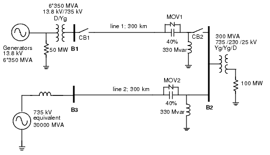
The single diagram shown here represents a three-phase, 60 Hz, 735 kV power system transmitting power from a power plant consisting of six 350 MVA generators to an equivalent network through a 600 km transmission line. The transmission line is split into two 300 km lines connected between buses B1, B2, and B3.
Figure 2-1: Series and Shunt Compensated Network
In order to increase the transmission capacity, each line is series compensated by capacitors representing 40% of the line reactance. Both lines are also shunt compensated by a 330 Mvar shunt reactance. The shunt and series compensation equipment is located at the B2 substation where a 300 MVA-735/230 kV transformer feeds a 230 kV-250 MW load through a 25 kV tertiary winding.
Each series compensation bank is protected by metal-oxide varistors (MOV1 and MOV2). The two circuit breakers of line 1 are shown as CB1 and CB2.
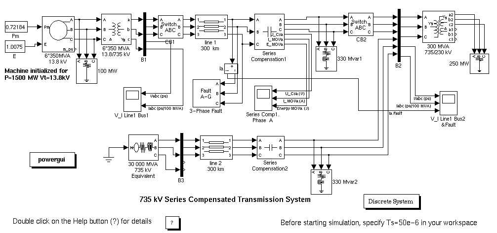
This network is available in the psb3phseriescomp model. Load this model and save it in your working directory as case1 in order to allow further modifications to the original system.
Compare the circuit modeled in Power System Blockset (Figure 2-2) with the schematic diagram of Figure 2-1. The generators are simulated with a Simplified Synchronous Machine block. A Three-Phase Transformer (Two-Windings) block and a Three-Phase Transformer (Three-Windings) block are used to model the two transformers. Saturation is implemented on the transformer connected at bus B2.
B1 and B3 blocks are Three-Phase V-I Measurement blocks taken from the Measurements library. B2 is a similar block that has been modified to accommodate two three-phase inputs and one three-phase output. These blocks are reformatted and given a black background color to give them the appearance of bus bars. They output the three line-to-ground voltages multiplexed on output 4 and the three line currents multiplexed on output 5. Open the dialog boxes of B1 and B2. See how the blocks are programmed to output voltages in p.u. and current in p.u./100 MVA.
The fault is applied on line 1, on the line side of the capacitor bank. Open the dialog boxes of the 3-Phase Fault block and of the 3-Phase breakers CB1 and CB2. See how the initial breaker status and switching times are specified. A line-to-ground fault is applied on phase A at t = 1 cycle. The two circuit breakers that are initially closed are then open at t = 5 cycles, simulating a fault detection and opening time of 4 cycles. The fault is eliminated at t = 6 cycles, one cycle after the line opening.
Figure 2-2: Series-Compensated Network (psb3phseriescomp.mdl)
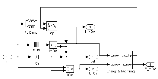
Series Compensation1 Subsystem
Now, open the Series Compensation1 subsystem of the psb3phseriescomp model. The three-phase module consists of three identical subsystems, one for each phase. A note indicates how the capacitance value and the MOV protection level are calculated. Open the Series Compensation1/ Phase A subsystem. You can see the details of the connections of the series capacitor and the Surge Arrester block (MOV block). The transmission line is 40% series compensated by a 62.8 µF capacitor. The capacitor is protected by the MOV block. If you open the dialog box of the MOV block, you will notice that it consists of 60 columns and that its protection level (specified at a reference current of 500 A/column or 30 kA total) is set at 298.7 kV. This voltage corresponds to 2.5 times the nominal capacitor voltage obtained at a nominal current of 2 kA rms.
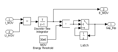
A gap is also connected in parallel with the MOV block. The gap is fired when the energy absorbed by the surge arrester exceeds a critical value of 30 MJ. In order to limit the rate of rise of capacitor current when the gap is fired, a damping RL circuit is connected in series. Open the Energy & Gap firing subsystem. It shows how the energy dissipated in the MOV is calculated by integrating the power (product of the MOV voltage and current).
When the energy exceeds the 30 MJ threshold, a closing order is sent to the breaker block simulating the gap.
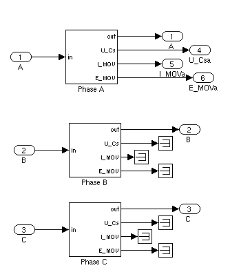
Figure 2-3: Series Compensation Module
Series Compensation1/PhaseA Subsystem:
Series Compensation1/PhaseA Subsystem/Energy & Gap firing:
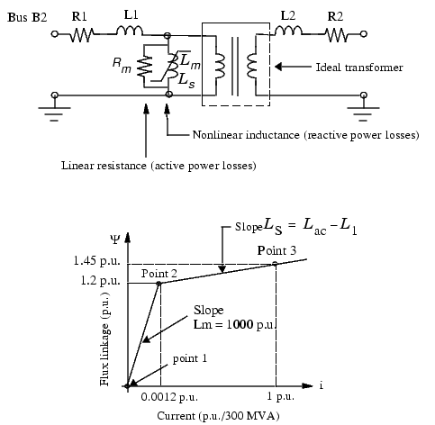
Three-Phase Saturable Transformer Model
Open the 300 MVA 735/230 kV Transformer dialog box and notice that the current-flux saturation characteristic is set at
These data are the current and flux values at points 1, 2, and 3 of the piecewise linear approximation to the flux linkage curve shown here:
Figure 2-4: Saturable Transformer Model
The flux-current characteristic is approximated by the two segments shown in the graph here. The saturation knee point is 1.2 p.u. The first segment corresponds to the magnetizing characteristic in the linear region (for fluxes below 1.2 p.u.). At 1 p.u. voltage, the inductive magnetizing current is 0.0010/1.0 = 0.001 p.u., corresponding to 0.1% reactive power losses.
The iron core losses (active power losses) are specified by the magnetization resistance Rm = 1000 p.u., corresponding to 0.1% losses at nominal voltage.
The slope of the saturation characteristic in the saturated region is 0.25 p.u. Therefore, taking into account the primary leakage reactance (L1 = 0.15 p.u.), the air core reactance of the transformer seen from the primary winding is 0.4 p.u./300 MVA.
| | Case Studies | Setting the Initial Load Flow and Obtaining Steady State | |