| SimPowerSystems |
  |
Controlled Voltage Source
Implement a controlled voltage source
Library
Electrical Sources
Description

The Controlled Voltage Source block provides a voltage source controlled by a Simulink signal.
You can initialize the Controlled Voltage Source block with a specific AC or DC voltage. If you want to start the simulation in steady state, the Simulink input must be connected to a signal starting as a sinusoidal or DC waveform corresponding to the initial values.
Dialog Box and Parameters

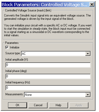
- Initialize
- If selected, initializes the Controlled Voltage Source block with the specified Initial voltage, Initial phase, and Initial frequency parameters.
- Source type
- The type of voltage source. Select AC to initialize the Controlled Voltage Source block with an AC voltage source. Select DC to initialize the Controlled Voltage Source Block with a DC voltage.
- The Source type parameter is not available in the dialog box if the Initialize parameter is not selected.
- Initial voltage
- The initial voltage for the initialization of the source, in amperes (A). The Initial voltage parameter is not available in the dialog box if the Initialize parameter is not selected.
- Initial phase
- The initial phase for the initialization of the source, in degrees. The Initial phase parameter is not available in the dialog box if the Source type parameter is set to DC.
- Initial frequency
- The initial frequency for the initialization of the source, in hertz (Hz). The Initial frequency parameter is not available in the dialog box if the Source type parameter is set to DC.
- Measurements
- Select Voltage to measure the voltage across the terminals of the Controlled Voltage Source block.
- Place a Multimeter block in your model to display the selected measurements during the simulation. In the Available Measurements list box of the Multimeter block, the measurement is identified by a label followed by the block name:
Measurement
|
Label
|
Voltage
|
Usrc:
|
Example
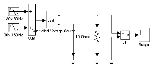
The psbcontrolvolt.mdl demo uses Controlled Voltage Source blocks to generate a 60 Hz sinusoidal voltage containing a third harmonic. One Controlled Voltage Source block is initialized as a 120 V AC voltage source with an initial frequency of 60 Hz and initial phase set to 0. The second Controlled Voltage Source block is not initialized.
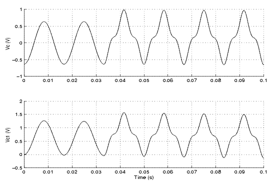
At t = 0.0333 s a 100 V-180 Hz sinusoidal signal is added to the 120 V Simulink signal. The resulting capacitor voltages are compared on a Scope block.

The Vc voltage starts in steady state, whereas the Vc1 voltage contains a DC offset.

See Also
AC Current Source, Controlled Current Source, Multimeter
 | Controlled Current Source | | Current Measurement |  |


![]()


