| SimMechanics |
  |
Modifying the Model
Here are two modifications of the demo you can try. One illustrates the simple user-driven controller you can adjust to change the motion of the pusher. The other illustrates a powerful feature of SimMechanics, visualization of a machine and animation of its simulated motion.
To make these modifications, it is best to close and restart the demo.
Changing the Pusher Reference Position
The Reference Position block is actually a Simulink Slider Gain block (from the Simulink Math Library) and controls where the pusher comes to rest.
You can adjust the Reference Position block to change where the pusher stops:
- Open the Reference Position block. You see an adjustable slider to set the position of the pusher's rest point.
- Enter values in the Low and High fields to set the lower and upper limits of the allowed slider range. The defaults in this demo are
0 and 0.2, with implied units of meters (m).
- Enter a value in the central field to set the pusher stopping point, which you can also adjust by clicking and dragging the slider between the lower and upper limits. The default is
0 (meters).
You can apply changes to the reference position to the simulation in two ways:
- Reset the Reference Position block first, then start the demo. You see the pusher trajectory track differently now, toward the new stopping point.
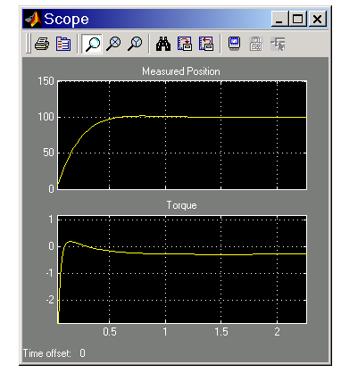
- Start the demo with the Reference Position block open and move the slider up and down as the simulation runs. Watch the Scope. The measured position and the necessary torque adjust to follow the new reference position.
Visualizing and Animating the Conveyor
You can visualize the conveyor mechanism as a static machine and animate the simulation as well with the two visualization tools:
With either visualization tool, you can display the bodies of the machine in two possible abstract representations:
- Equivalent ellipsoids use the inertia tensors and masses of the bodies. Each body has a unique homogeneous ellipsoid equivalent to it in mass and inertia tensor.
- Convex hulls use the attached Body coordinate systems (CSs) of the bodies. A body must have at least four non-coplanar Body CS origins to enclose a convex hull with nonzero volume. If the Body has fewer than four Body CS origins or if the origins are coplanar or collinear or coincident, the visualization tools render it with simpler figures (triangle, line, or point).
Handle Graphics Visualization. First try visualizing the conveyor with Handle Graphics:
- From the Simulation menu, click Mechanical environment. The Mechanical Environment Settings dialog box appears.
- Click the Visualization tab. Select the Draw machine in initial state and Animate machine during simulation check boxes.
- Leave the other defaults as they are and close the dialog.
Visualization Control
|
Default Value
|
Draw machine using
|
MATLAB Graphics
|
Represent bodies as
|
Convex hulls
|
Update machine
|
When diagram changes
|
- A MATLAB Handle Graphics window appears, displaying the conveyor machine at rest in its initial state.
The bodies are rendered in the default representation, as convex hulls. The bodies and Body coordinate system axis triads are also displayed as defaults.
- Change Reference Position to a nonzero value such as
0.1 or 0.2.
- Restart the simulation. The Handle Graphics window animates the machine in motion. You can compare this motion to the plots in the scope.
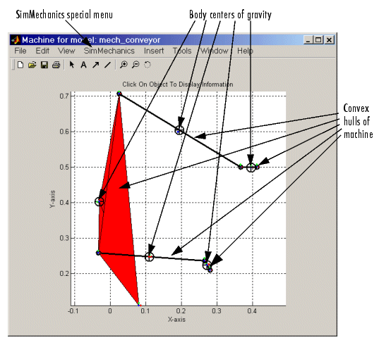
- Click a body in the Handle Graphics window. The model window comes back into focus with the corresponding Body block highlighted in color.
- Open the special SimMechanics menu in the upper right of the Handle Graphics window.
- Here, you can reconfigure the special display properties for machines: bodies, Body CS axis triads, colored fill-in patches connecting Body CSs on the same body, and user viewpoint orientation.
- Close the Handle Graphics window when you are finished.
Virtual Reality Visualization. Now visualize the conveyor in virtual reality scene:
- From the Simulation menu, click Mechanical environment. The Mechanical Environment Settings dialog box appears.
- Click the Visualization tab. Select the Draw machine in initial state and Animate machine during simulation check boxes.
- Using the pull-down menus, change Draw machine using to
Virtual Reality Toolbox and Represent bodies as to Equivalent ellipsoids.
- Leave Update machine as
When diagram changes.
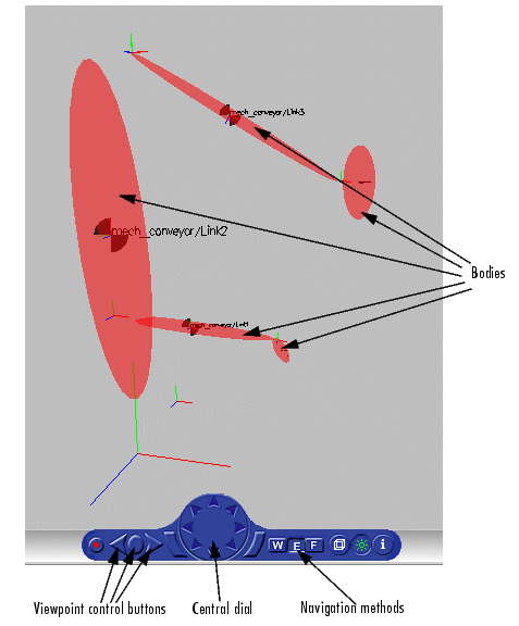
A virtual reality viewer opens, displaying the conveyor machine at rest in its initial state.
The bodies are rendered as equivalent ellipsoids.
- Restart the simulation. The viewer now animates the machine in motion.
- Use the virtual reality controls at the bottom of the virtual scene to change the user viewing position and orientation:
- Moving the central dial pointer around the outside of the dial circle, you can change the direction of your movement. Pressing the dial pointer itself, you then move in that direction.
- Left-clicking and rolling your mouse in the scene changes your viewpoint.
- Right-clicking in the scene opens the control menu.
- See Viewing Machines in Virtual Reality in the Visualizing and Animating Machines chapter for how to control the virtual scene.
- While the animation is running, open the Reference Position block and move the slider up and down. In addition to what you can see in the Scope plots, the viewer directly animates the pusher trajectory in space as the mechanism responds to your adjustment.
| | Starting the Demo | | What Can You Do with SimMechanics? | |