| SimMechanics |
  |
Body
Represent a customizable rigid body
Library
Bodies
Description

The Body block represents a rigid body whose properties you customize. The representation you specify includes:
A rigid body is defined in space by the position of its CG (or center of mass) and its orientation in some CS.
| Setting Body Initial Conditions
The initial position and orientation of a body are set by the entries in its Body dialog. These initial conditions remain unchanged; unless, with a Joint Initial Condition Actuator, you change the initial conditions of the Joint(s) connected to the Body prior to starting the simulation, or you actuate the Body with a Body Actuator. |
In SimMechanics, you enter the body's properties in two classes, the geometric properties and the mass properties:
- The geometric properties are defined by the body's Body CSs.
- The minimum required Body CS is the CS with its origin at the CG. The CG point specifies both the initial position of the whole body and the origin of the CG CS. You must also orient the CG CS axes.
- You can place any number of additional Body CSs on a body. You must define each Body CS by the position of its origin and the orientation of its CS axes.
- Each connection of a Joint, Constraint/Drive, Actuator, or Sensor block to a Body requires an anchor point on the Body. This anchor point is one of the Body CS origins.
- Body CSs on the block available for connections are shown by Body CS ports
 on the sides of the block. You can show or hide each Body CS on the block sides.
- The set of a body's Body CS origins (including the CG CS) defines the body's convex hull, one of the visualization shapes available for representing a body in space.
- The mass properties are defined by the body's mass and inertia tensor.
- The mass is the body's inertia and controls the translational acceleration of the CG in response to an applied force.
- The inertia tensor measures the distribution of mass density in the body and controls the rotational acceleration of the body about the CG in response to an applied torque.
- The components of the inertia tensor control the initial orientation of the body and are always interpreted as being in the CG CS axes. The orientation of the CG CS axes with respect to another CS external to the body (the World CS, a CS on a Ground, or a CS on another Body) then determines the orientation of the body with respect to other bodies or with respect to World.
- The body's inertia tensor defines its principal axes and moments and its equivalent ellipsoid, one of the visualization shapes available for representing a body in space.
Default Initial State of a Body
These two sets of properties determine a body's initial position and orientation:
- The initial position of a body is set by the position of its CG.
- The initial orientation is set by its inertia tensor components (in the CG CS) and the orientation of the CG CS axes with respect to other CSs in the machine.
The initial conditions of a machine can be changed with Joint Initial Condition Actuator blocks before starting a simulation. If you do not change the initial state of a Body before simulation, SimMechanics sets its initial position/orientation to its Body dialog box entries. SimMechanics also sets the Body's initial linear/angular velocities to zero in this case.
Dialog Box and Parameters
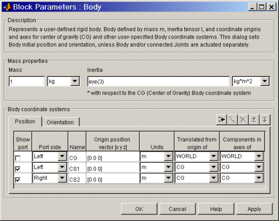
The dialog box has two active areas, Mass Properties and Body Coordinate Systems.
Mass Properties
- Mass
- Enter the mass of the body in the first field and choose units in the pull-down menu to the right. The mass must be a positive, real number or MATLAB equivalent. The defaults are 1 and kg (kilograms).
- Inertia tensor
- Enter the inertia tensor (with respect to the Body CG CS axes) in the first field and choose units in the pull-down menu to the right. The tensor must be a 3-by-3 real, symmetric matrix. The default tensor is eye(3), the MATLAB 3-by-3 identity matrix. A zero tensor
zeros(3,3) defines a point mass. The units default is kg-m2 (kilograms-meters2).
Body Coordinate Systems
Configuring a Body Coordinate System
You set up Body CSs in the Body coordinate systems area:
- The default configuration consists of three Body CSs: the required CG CS attached to the body's CG and two other optional Body CSs, called "CS1" and "CS2", for connecting Joints, Constraints, or Drivers.
- You can configure the CG CS but not delete it. You also cannot create additional CG CSs, although you can duplicate the CG CS with a different name. (See following.)
- The other CSs can be configured or deleted as you want.
- Configuring a Body CSs requires two groups of steps:
- positioning the Body CS origin in the Position panel
- orienting the Body CS axes in the Orientation panel.
- Defining Body CSs requires referring to other, pre-existing CSs in the model. In a given Body block, you can refer to Body and grounded CSs in three ways. The references must be to:
- World
- Other Body CSs on the same body
- The Adjoining CS, the coordinate system on a neighboring body or ground directly connected to the selected Body CS by a Joint, Constraint, or Driver.
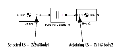
- Toggle between the Position or Orientation panels with the tabs.
- Each Body CS is labeled with a name,
CG for the CG CS, and CS1, CS2, etc., for additional CSs.
Configuring the Position fields
The Position fields for each Body CS specify the position of that CS's origin as a translation vector:
- The numerical components of the vector carry units.
- The origin is displaced from the origin of another, pre-existing CS in your machine by this translation vector.
- The translation vector's components are oriented with respect to another set of CS axes.
Highlight each Body CS to configure it.
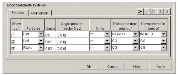
- Origin position vector [x y z]
- Enter the translation vector that defines the position of the Body CS's origin.
- The special entry for the CG CS origin places the entire body.
- Units
- Choose linear units for the translation vector. The default is m (meters).
- Translated from the origin of
- In the pull-down menu, choose the other, pre-existing CS in your machine that defines the starting point for the translation vector. The choices are
WORLD, ADJOINING, and the other Body CSs on this Body. The ending point of the translation vector is this Body CS's origin.
- For the CG CS, the default starting-point CS is
WORLD. For the additional Body CSs (CS1, CS2, etc.), the default starting point CS is this Body's CG.
- Components in the axes of
- In the pull-down menu, choose the CS whose axes define the orientation of the translation vector's components. The choices are
WORLD, ADJOINING, and the other Body CSs on this Body. The translation vector's components are projected along the axes of the CS chosen in this column.
- For the CG CS, the default orientation CS is
WORLD. For the additional Body CSs (CS1, CS2, etc.), the default orientation CS is this Body's CG.
Configuring the Orientation Fields
The Orientation fields for each Body CS specify the orientation of that CS's triad of axes as a rotation:
- The orientation vector specifying the rotation vector has three components.
- The numerical components of the vector carry units.
- The rotation is oriented with respect to some other, pre-existing set of CS coordinate axes in your machine.
- The orientation vector's components are interpreted in the convention of a rotation representation.
Highlight each Body CS to configure it.
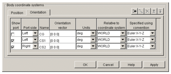
- Orientation vector
- Enter the components of the rotation that defines the orientation of the Body CS's axes. The geometric meaning of these components is determined by the Specified using convention column.
- The special entry for the CG CS orients the CG CS axes. Together with the Inertia tensor entry in Mass properties, the CG CS axes orient the whole body with respect to another CS in your machine.
- Units
- Choose angular units for the rotation, degrees or radians. The default is
deg (degrees).
- Relative to coordinate system
- In the pull-down menu, choose the other, pre-existing CS in your machine that defines the starting orientation for the rotation. The choices are
WORLD, ADJOINING, and the other Body CSs on this Body.
- Specified using convention
- In the pull-down menu, choose the representation type for the rotation:
Rotation Type
|
Orientation vector components
|
Quaternion
|
[nx*sin( /2) ny*sin( /2) nz*sin( /2) cos( /2)]
|
3x3Transform
|
3-by-3 orthogonal rotation matrix R
|
Euler
|
Rotation angles about: [X-axis Y-axis Z-axis]
|
Rotation Conventions
There are three generic conventions for representing rotations:
- The Euler angle convention specifies the rotation of the Body CS axes by rotating about three axes in a sequence. The components of the 1-by-3 row vector are the angles of rotation about the X-, Y-, and Z-axes, respectively, in degrees or radians.
For example, Euler X-Y-Z means, rotate about the original X-axis, then about the intermediate Y-axis, and then about the next intermediate Z-axis. Another example: Euler X-Z-Y means, rotate about the original X-axis, then about the intermediate Z-axis, and then about the next intermediate Y-axis.
- The quaternion convention specifies the rotation in angle-axis form as a dimensionless 1-by-4 row vector:
[nx*sin(
/2) ny*sin(
/2) nz*sin(
/2) cos(
/2)]
Managing the Body Coordinate Systems List
The Body coordinate system controls (see the following Body coordinate systems controls figure) allow you to add, duplicate, reorder, and delete Body CSs on a Body block:
- To add a Body CS to the list:
A new Body CS will appear immediately below the Body CS you highlighted. New Body CSs are named in sequence after the current ones: CS3, CS4, etc.
- To duplicate a Body CS in the list:
A new Body CS with the same configuration but a different name will appear immediately below the Body CS you highlighted. New Body CSs are named in sequence after the current ones: CS3, CS4, etc.
- To change the position of a Body CS in the list:
- Highlight the Body CS whose position you want to change.
- Click on the Up or Down button (see the following Body coordinate systems controls figure) until the Body CS is where you want it.
- To delete a Body CS from the list:
- You cannot delete the Body's CG CS.
Managing Body CS Ports on a Body Block
To connect a Joint, Constraint/Driver, Actuator, or Sensor block to a Body block requires an existing and configured Body CS in the Body to anchor the other block to:
- These other blocks define, constraint, impart, and measure the motion of bodies with respect to the origin and coordinate axes of Body CSs. Connect each of these blocks to a Body CS with a connection line.
- The actual connection line running from the other block to the Body block must be anchored to a displayed Body CS Port
 on the side of the Body block in the model window.

- A displayed Body CS Port on a Body block indicates a Body CS with the displayed name configured internally within the Body block.
- Not all the Body CSs configured inside a Body block need to be displayed, however.
- Show port
- Select this check box for any Body CS to create a corresponding Body CS Port
 on the side of the Body block. The Body CS on that line in the Body CS list is now accessible for connection to other blocks.
- Unselect this check box to remove the Body CS Port corresponding to that Body CS on that line in the list.
- The defaults are: unselected for
CG, selected for CS1 and CS2.
- To apply your choices to the displayed Body block, click Apply.
- Port side
- From the pull-down menu, choose which side of the Body block you want the Body CS Port for that Body CS to be placed on,
Left or Right.
- The defaults are
Left for CG and CS1 and Right for CS2.
- To apply your choices to the displayed Body block, click Apply.
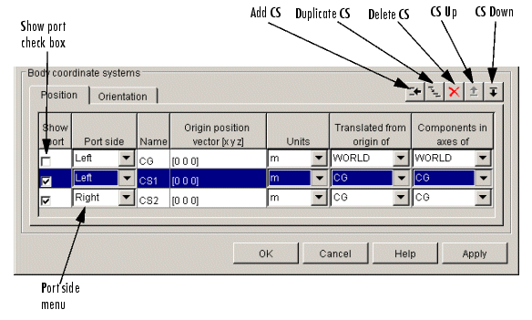
Body coordinate systems controls
See Also
Body Actuator, Body Sensor, Body Sensor, Ground
See Modeling Bodies, Creating Body CS Ports, and Choosing Visualization Options in SimMechanics for more on setting up Bodies in machines.
See Modeling Sensors for setting general initial conditions (positions and velocities) of DoFs in a machine.
 | Bearing | | Body Actuator |  |


 on the sides of the block. You can show or hide each Body CS on the block sides.


 and follows the right-hand rule.
 on the side of the Body block in the model window.
 on the side of the Body block. The Body CS on that line in the Body CS list is now accessible for connection to other blocks.
