| Embedded Target for Motorola MPC555 | |
Configure a Vector CAN channel (either hardware or virtual) for use with Vector-Informatik drivers
Library
Description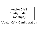
The Vector CAN Configuration block configures a CAN channel on the host PC, using the Vector CAN Driver. A CAN channel can be
The Vector CAN Driver software must be installed on your PC, regardless of whether you want to use virtual channels or actual hardware.
Place one Vector CAN Configuration block in the model for each CAN channel required.
You can use virtual channels to communicate between two separate Simulink models in the same MATLAB session, or between a CANalyser session and Simulink, or even between two Simulink models running in different sessions of MATLAB on the same machine. For an example of how this can be done see the mpc555rt_io and mpc555rt_iohost demos.
A Vector CAN Configuration block works in association with Vector CAN Transmit and Vector CAN Receive blocks. The association is formed by assigning the same values to the Tag parameter of all the blocks.
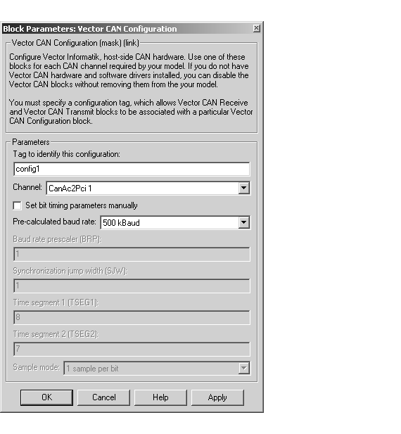
Setting the Baud Rate
The Vector CAN Configuration block lets you set the speed of the CAN channel connection.
In many cases you can avoid the complexities of CAN bit timing by selecting one of the Precalculated baud rate settings in the Block Parameters dialog box. We recommend using the precalculated baud rates wherever possible.
If the precalculated baud rates do not meet your requirements, you can select the Set bit timing parameters manually option. You can then set the baud rate by configuring the Baud rate prescaler, Synchronization jump width, Time segment 1, Time segment 2, and Sample mode parameters as described in this section.
The following variables are defined in calculating the baud rate for the Vector CAN Configuration block:
[1..64].
[1..16].
[1..8].
To set the baud rate, first derive values for prescaler, tseg1, and tseg2, using the following formulas:
Next, select values for the following parameters:
1 sample per bit or 3 samples per bit, via the drop down menu. 3 samples per bit is more reliable, and may be necessary on a noisy channel.
Finally, enter the values derived above into the block parameters:
As an example, the parameters used for the precalculated baud rate 500 kBaud were
1
8.
7.
1 sample per bit
For further information on the CAN, and on CAN bit timing, see the following documents, available at the CAN in Automation (CiA) Web site: http://www.can-cia.de
Dialog Box
Virtual 1 or Virtual 2) or a supported hardware device.Virtual 1 or Virtual 2. None. This allows you to use the block in simulation, even without the required driver or hardware installed. If you select a hardware device and the driver detects that you do not have the requested hardware installed, the block will report an error during simulation.| | TouCAN Warnings | Vector CAN Receive | |