| DSP Blockset |
  |
Interpolation
Interpolate values of real input samples
Library
Signal Operations
Description

The Interpolation block interpolates each channel of discrete, real, inputs using linear or FIR interpolation. The input can be a sample- or frame-based vector or matrix. The output is a vector or matrix of the interpolated values, and has the same frame status and frame rate as the input.
You must specify the interpolation points (times at which to interpolate values) in an interpolation vector, In. An entry of 1 in In refers to the first sample of the input, an entry of 2.5 refers to the sample half-way between the second and third input sample, and so on. In must have the same frame status and frame rate as the input, and can be a length-P row or column vector, where P is usually any positive integer.
Usually, the block applies the vector In to each column of an input matrix, or to each input vector. You can set the block to either apply the same interpolation vector for all input vectors or matrices (static interpolation points), or use a different interpolation vector for each input vector or matrix (time-varying interpolation points).
For more information, see other sections of this reference page.
Sections of This Reference Page
Specifying Static Interpolation Points
To supply the block with a static interpolation vector (an interpolation vector applied to every input vector or matrix), do the following:
Specifying Time-Varying Interpolation Points
To supply the block with time-varying interpolation vectors (where the block uses a different interpolation vector for each input vector or matrix), do the following:
- Set the Source of interpolation points parameter to Input port, which activates a block input port, In, for the interpolation points.
- Generate a signal of interpolation vectors with the same frame status and same frame rate as the input signal, and supply it to the input port for interpolation points. To learn about interpolation vectors, see How the Block Applies Interpolation Vectors to Inputs.
How the Block Applies Interpolation Vectors to Inputs
The interpolation vector In represents the points in time at which to interpolate values of the input signal. An entry of 1 in In refers to the first sample of the input, an entry of 2.5 refers to the sample half-way between the second and third input sample, and so on. In most cases, the vector In can be of any length.
Depending on the dimension and frame status of the input and the dimension of In, the block usually applies In to the input in one of the following ways:
- Apply the vector In to each channel of a matrix input, resulting in a matrix output.
- Apply the vector In to each input vector (as if the input vector were a single channel), resulting in a vector output with the same orientation as the input (row or column).
The following tables summarize how the block applies the vector In to all the possible types of sample- and frame-based inputs, and show the resulting output dimensions. (The block applies both static and time-varying interpolation vectors to the input signal in the same way).
Table 7-12: How Block Applies Interpolation Vectors to Frame-Based Inputs
Frame-Based Input Dimensions
|
Dimensions of Interpolation Vector In
P is a positive integer
|
How Block Applies In to Input
|
Frame-Based Output Dimensions
|
M-by-N matrix
| P-by-1 column
|
Applies In to each input column
|
P-by-N matrix
|
1-by-N row
|
Applies each column of In (each element of In) to the corresponding columns of the input
|
1-by-N row
|
M-by-1 column
| P-by-1 column
|
Applies In to the input column
|
P-by-1 column
|
1-by-P row
(block treats as a column)
|
Applies In to the input column
|
P-by-1 column
|
1-by-N row
(not recommended)
| P-by-1 column
|
not applicable
|
P-by-N matrix where each row is a copy of the input vector
|
1-by-P row
|
not applicable
|
1-by-N row, a copy of the input vector
|
Table 7-13: How Block Applies Interpolation Vectors to Sample-Based Inputs
Sample-Based Input Dimensions
|
Dimensions of Interpolation Vector In
P is any positive integer
|
How Block Applies In to Input
|
Sample-Based Output Dimensions
|
M-by-N matrix
| P-by-1 column
|
Applies In to each input column
|
P-by-N matrix
|
1-by-P row
(block treats as a column)
|
Applies In to each input column
|
P-by-N matrix
|
M-by-1 column
| P-by-1 column
|
Applies In to the input column
|
P-by-1 column
|
1-by-P row
(block treats as a column)
|
Applies In to the input column
|
P-by-1 column
|
1-by-N row
| P-by-1 column
(block treats as a row)
|
Applies In to the input row
|
1-by-P row
|
1-by-P row
|
Applies In to the input row
|
1-by-P row
|
Handling Out-of-Range Interpolation Points
The valid range of the values in the interpolation vector In is from 1 to the number of samples in each channel of the input. For instance, given a length-5 input vector D, all entries of In must range from 1 to 5. In cannot contain entries such as 7 or -9, since there is no 7th or -9th entry in D.
The Out of range interpolation points parameter sets how the block handles interpolation points that are not within the valid range, and has the following settings:
- Clip -- The block replaces any out-of-range values in In with the closest value in the valid range (from 1 to the number of input samples), and then proceeds with computations using the clipped version of In.
- Clip and warn -- In addition to Clip, the block issues a warning at the MATLAB command line every time clipping occurs.
- Error -- When the block encounters an out-of-range value in In, the simulation stops and the block issues an error at the MATLAB command line.
Example of Clipping . Suppose the block is set to clip out-of-range interpolation points, and gets the following input vector and interpolation points:
D = [11, 22, 33, 44]'
In = [10, 2.6, -3]'
Since D has 4 samples, valid interpolation points range from 1 to 4. The block clips the interpolation point 10 to 4 and the point -3 to 1, resulting in the clipped interpolation vector Inclipped = [4, 2.6, 1]'.
Linear Interpolation Mode
When Interpolation Mode is set to Linear, the block interpolates data values by assuming that the data varies linearly between samples taken at adjacent sample times.
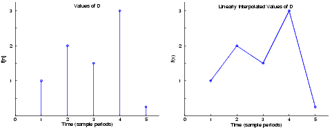
For instance, if the input signal D = [1, 2, 1.5, 3, 0.25]', the following left-hand plot shows the samples in D, and the right-hand plot shows the linearly interpolated values between the samples in D.

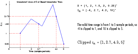
As illustrated below, if the block is in linear interpolation mode and is set to clip out-of-range interpolation points, where
D = [1, 2, 1.5, 3, 0.25]'
In = [-4, 2.7, 4.3, 10]'
then the block clips the invalid interpolation points, and outputs the linearly interpolated values in a vector, [1, 1.65, 2.175, 0.25]'.

FIR Interpolation Mode
When Interpolation Mode is set to FIR, the block interpolates data values using an FIR interpolation filter, specified by various block parameters. See the topic on FIR Interpolation Mode in the Variable Fractional Delay block reference for more information.
Dialog Box

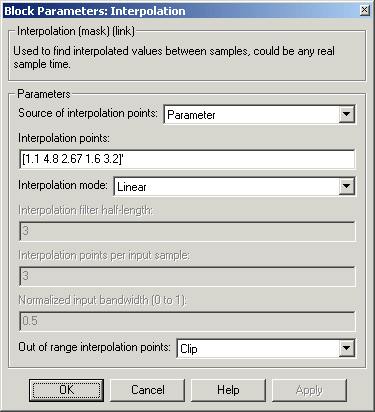
- Source of interpolation points
- Sets the location for specifying interpolation points (the points in time at which to interpolate the input): either in a dialog parameter (for static interpolation points) or a block input port (for time-varying interpolation points). For more information, see Specifying Static Interpolation Points and Specifying Time-Varying Interpolation Points. Tunable.
- Interpolation points
- The vector In of points in time at which to interpolate the input signal. An entry of 1 in In refers to the first sample of the input, an entry of 2.5 refers to the sample half-way between the second and third input sample, and so on. See How the Block Applies Interpolation Vectors to Inputs. Tunable.
- Interpolation mode
- Sets the block to interpolate by either linear or FIR interpolation. For more information, see Linear Interpolation Mode and FIR Interpolation Mode.
- Interpolator filter half-length
- Half the length of the FIR interpolation filter. For more information, see FIR Interpolation Mode.
- Interpolation points per input sample
- The number Q, where the FIR interpolation filter uses the nearest 2*Q points in the signal to interpolate the value at an interpolation point. If there are less than 2*Q neighboring points, the block uses linear interpolation in place of FIR interpolation. For more information, see FIR Interpolation Mode. and Linear Interpolation Mode.
- Normalized input bandwidth (0 to 1)
- The bandwidth of the input divided by Fs/2 (half the input sample frequency). For more information, see FIR Interpolation Mode.
- Out of range interpolation points
- If an interpolation point is out of range, this parameter sets the block to either clip the interpolation point, clip the value and issue a warning at the MATLAB command line, or stop the simulation and issue an error at the MATLAB command line. For more information, see Handling Out-of-Range Interpolation Points.
Supported Data Types
- Double-precision floating point
- Single-precision floating point
To learn how to convert to the above data types in MATLAB and Simulink, see Supported Data Types and How to Convert to Them.
See Also
See Signal Operations for a list of all the blocks in the Signal Operations library.
 | Integer Delay | | Kalman Adaptive Filter |  |


