
| DSP Blockset |   |
Compute the IFFT of the input.
Library
Description![]()
The IFFT block computes the inverse fast Fourier transform (IFFT) of each channel in the M-by-N or length-M input, u, where M must be a power of two. To work with other input sizes, use the Zero Pad block to pad or truncate the length-M dimension to a power-of-two length. The output is always frame-based, and each output column contains the M-point inverse discrete Fourier transform (IDFT) of the corresponding input channel.
The kth entry of the lth output channel, y(k, l), is the kth point of the M-point IDFT of the lth input channel.

|
(7-3) |
You can choose to output a scaled version of the input's IDFT,  , by setting the parameter Skip normalization by transform length, N.

|
(7-4) |
For information on block output characteristics and how to configure the block computation methods, see other sections of this reference page.
Sections of This Reference Page
Input and Output Characteristics
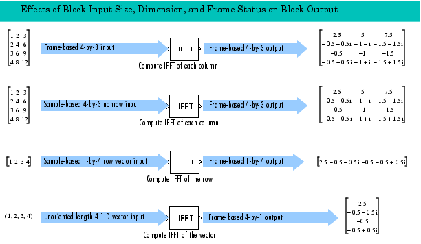
The following table describes all valid block input types, their corresponding outputs, and the dimension along which the block computes the IDFT.
| Note For M-by-N and length-M inputs, M must be a power of two. To work with other input sizes, use the Zero Pad block to pad or truncate the length-M dimension to a power-of-two length. To get valid outputs, you must correctly set the Input is in bit-reversed order parameter to indicate the ordering of the block input. When the input is conjugate symmetric and you want to get a real-valued output, set the Input is conjugate symmetric parameter. |
| Valid Block Inputs |
Dimension Along Which Block Computes IDFT |
Corresponding Block Output Characteristics Output port rate = input port rate |
| Frame-based M-by-N matrix |
Column |
The following output characteristics apply to all valid block inputs:
|
Sample-based M-by-N matrix,  |
Column |
|
| Sample-based 1-by-M row vector |
Row |
|
| 1-D length-M vector |
Vector |
Click here in the MATLAB Help Browser to open a Simulink model based on the following diagram.

Conjugate Symmetric Input
When the block input is conjugate symmetric and you want real-valued outputs, set the Input is conjugate symmetric parameter, which also optimizes the block's computation method. A common source of conjugate symmetric data is the FFT block, which yields conjugate symmetric output when its input is real-valued.
Inputs in Bit-Reversed Order
When the block input is in bit-reversed order, you must set the parameter Input is in bit-reversed order to get a valid output. The block output is invalid if you set this parameter when the input is not in bit-reversed order. A common source of bit-reversed inputs is the FFT block, as illustrated in the FFT block example, Use of Outputs in Bit-Reversed Order.
For a definition of bit-reversed and linear order, see the FFT block reference page section, Description of Bit-Reversed Ordering.
Selecting the Twiddle Factor Computation Method
The FFT block and IFFT block both have a parameter, Twiddle factor computation. Setting this parameter in the IFFT block is very similar to setting it in the FFT block. For details, see the FFT block reference page section, Selecting the Twiddle Factor Computation Method.
Optimizing the Table of Trigonometric Values
The FFT block and IFFT block both have a parameter, Optimize table for. Setting this parameter in the IFFT block is very similar to setting it in the FFT block. For details, see the FFT block reference page section, Optimizing the Table of Trigonometric Values.
Algorithms Used for IFFT Computation
Depending on whether the block input is real- or complex-valued and conjugate symmetric, the block uses one or more of the following algorithms as summarized in the next table:
Example
For an example of how to optimize computations when using both the IFFT block and FFT block in the same model, see the FFT block reference page example, Use of Outputs in Bit-Reversed Order.
Dialog Box
 in Equation 7-3. In Table lookup mode, the block computes and stores the sine and cosine values before the simulation starts. In Trigonometric fcn mode, the block computes the sine and cosine values during the simulation.
 Supported Data Types
To learn how to convert to the above data types in MATLAB and Simulink, see Supported Data Types and How to Convert to Them.
See Also
| FFT |
DSP Blockset |
| IDCT |
DSP Blockset |
| Pad |
DSP Blockset |
| Zero Pad |
DSP Blockset |
bitrevorder |
Signal Processing Toolbox |
fft |
Signal Processing Toolbox |
ifft |
Signal Processing Toolbox |
Also see Transforms for a list of all the blocks in the Transforms library.
 | IDWT | Inherit Complexity |  |