| DSP Blockset | |
Upsample, filter, and downsample an input signal.
Library
Filtering / Multirate Filters
Description
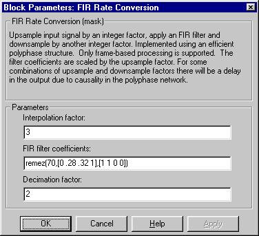
The FIR Rate Conversion block resamples the discrete-time input to a period K/L times the input sample period, where the integer K is specified by the Decimation factor parameter and the integer L is specified by the Interpolation factor parameter. The resampling process consists of the following steps:
K and L must be relatively prime integers; that is, the ratio K/L cannot be reducible to a ratio of smaller integers. The FIR Rate Conversion block implements the above three steps together using a polyphase filter structure, which is more efficient than straightforward upsample-filter-decimate algorithms. The output of the interpolator is the first filter phase, while the output of the decimator is the last filter phase. When both K and L are greater than 1, the resulting output is the last decimation phase from the first interpolation phase.
The FIR filter coefficients parameter specifies the numerator coefficients of the FIR filter transfer function H(z).
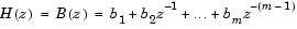
The coefficient vector, [b(1) b(2) ... b(m)], can be generated by one of the filter design functions in the Signal Processing Toolbox (such as fir1), and should have a length greater than the interpolation factor (m>L). The filter should be lowpass with normalized cutoff frequency no greater than min(1/L,1/K). All filter states are internally initialized to zero.
Frame-Based Operation
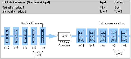
This block accepts only frame-based inputs. An Mi-by-N frame-based matrix input is treated as N independent channels, and the block resamples each channel independently over time.
The Interpolation factor, L, and Decimation factor, K, must satisfy the relation

for an integer output frame size Mo. The simplest way to satisfy this requirement is to let the Decimation factor equal the input frame size, Mi. The output frame size, Mo, is then equal to the Interpolation factor. This change in the frame size, from Mi to Mo, produces the desired rate conversion while leaving the output frame period the same as the input (Tfo = Tfi).
Latency
The FIR Rate Conversion block has no tasking latency. The block propagates the first filtered input (received at t=0) as the first output sample.
Examples
The dspsrcnv demo compares sample rate conversion performed by the FIR Rate Conversion block with the same conversion performed by a cascade of Upsample, Digital Filter, and Downsample blocks.
Diagnostics
An error is generated if the relation between K and L shown above is not satisfied.
A warning is generated if L and K are not relatively prime; that is, if the ratio L/K can be reduced to a ratio of smaller integers.
Warning: Integer conversion factors are not relatively prime in block 'modelname/FIR Rate Conversion (Frame)'. Converting ratioL/Mtol/m.
The block scales the ratio to be relatively prime, and continues the simulation.
Dialog Box
References
Fliege, N. J. Multirate Digital Signal Processing: Multirate Systems, Filter Banks, Wavelets. West Sussex, England: John Wiley & Sons, 1994.
Supported Data Types
To learn how to convert to the above data types in MATLAB and Simulink, see Supported Data Types and How to Convert to Them.
See Also
| Downsample |
DSP Blockset |
| FIR Decimation |
DSP Blockset |
| FIR Interpolation |
DSP Blockset |
| Upsample |
DSP Blockset |
fir1 |
Signal Processing Toolbox |
fir2 |
Signal Processing Toolbox |
firls |
Signal Processing Toolbox |
remez |
Signal Processing Toolbox |
upfirdn |
Signal Processing Toolbox |
See the following sections for related information:
| | FIR Interpolation | Flip | |