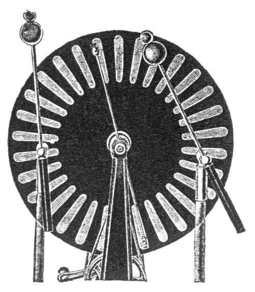
Operation of the Wimshurst machine
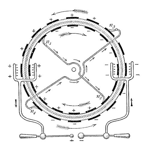 The Wimshurst
machine is an "influence machine", an electrostatic generator that uses
the charges already present on it to generate more charges by
electrostatic induction. It does not rely on friction for its operation.
Consider that the machine is charged as in the schematic representation,
shown (with cylinders instead of disks) with each half of each disk with
one polarity, with boundaries at the neutralizing bars. Ignore the charge
collectors and the output circuit. The two neutralizer bars are shown
floating, but it makes no difference in the operation if they are
grounded. At top and bottom, the charges are opposite, and at the sides
equal. With any small initial charge unbalance, the machine will quickly
fall into this configuration. After this occurs, when a sector touches a
neutralizing brush charge is attracted to it, with polarity opposite to
the charges at the other disk, due to the influence of the electric field
generated by the surrounding sectors. Since there are several sectors
inducing charge in just one sector, more charge than is present in each of
the opposite sectors is attracted, provided that the disks and sectors are
at sufficiently small distance. The effect is that progressively larger
charges are attracted to the neutralized sectors as the disks turn, and
the voltages at all fixed sector positions grow exponentially. The buildup
stops when the charge density on the sector surfaces creates an electric
field intense enough to cause breakdown in the air around, usually just
before they reach the neutralizing brushes. The machine then operates
generating a constant current at the output circuit, with maximum voltage
limited by sparking through the path formed by a series of sectors and a
neutralizer rod, or by other losses in the structure due to insufficient
insulation. Note that the induction from the adjacent sectors in the same
disk is important. The sectors before a sector touching a neutralizer, and
also the charge collector assemblies and sectors at the sides of the
disks, generate intense electric field, and help in the induction. The
sectors ahead have their prejudicial effect reduced by the oppositely
charged sectors in the other disk. The machine is self-starting,
because there is always some natural imbalance in the charges. The use of
different metals in the sectors and in the neutralizing brushes helps the
startup process due to contact potential developed when different metals
touch.
The Wimshurst
machine is an "influence machine", an electrostatic generator that uses
the charges already present on it to generate more charges by
electrostatic induction. It does not rely on friction for its operation.
Consider that the machine is charged as in the schematic representation,
shown (with cylinders instead of disks) with each half of each disk with
one polarity, with boundaries at the neutralizing bars. Ignore the charge
collectors and the output circuit. The two neutralizer bars are shown
floating, but it makes no difference in the operation if they are
grounded. At top and bottom, the charges are opposite, and at the sides
equal. With any small initial charge unbalance, the machine will quickly
fall into this configuration. After this occurs, when a sector touches a
neutralizing brush charge is attracted to it, with polarity opposite to
the charges at the other disk, due to the influence of the electric field
generated by the surrounding sectors. Since there are several sectors
inducing charge in just one sector, more charge than is present in each of
the opposite sectors is attracted, provided that the disks and sectors are
at sufficiently small distance. The effect is that progressively larger
charges are attracted to the neutralized sectors as the disks turn, and
the voltages at all fixed sector positions grow exponentially. The buildup
stops when the charge density on the sector surfaces creates an electric
field intense enough to cause breakdown in the air around, usually just
before they reach the neutralizing brushes. The machine then operates
generating a constant current at the output circuit, with maximum voltage
limited by sparking through the path formed by a series of sectors and a
neutralizer rod, or by other losses in the structure due to insufficient
insulation. Note that the induction from the adjacent sectors in the same
disk is important. The sectors before a sector touching a neutralizer, and
also the charge collector assemblies and sectors at the sides of the
disks, generate intense electric field, and help in the induction. The
sectors ahead have their prejudicial effect reduced by the oppositely
charged sectors in the other disk. The machine is self-starting,
because there is always some natural imbalance in the charges. The use of
different metals in the sectors and in the neutralizing brushes helps the
startup process due to contact potential developed when different metals
touch.
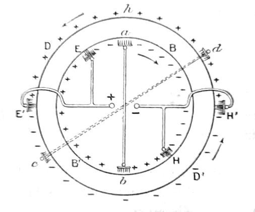
The machine still works with just one disk
turning, if the other is stopped and kept charged in some way. This idea
is the base of the older machines of Holtz, Voss, and others, that use a rotating disk and a
fixed disk with inductor plates. The elegant design of the Wimshurst
machine uses the same disks to generate new charges and to induce charges,
and keeps all the parts of the disks alternating polarity twice at each
turn. This is important to avoid charge buildup at the unused sides of the
disks, what in the machines with fixed inductors eventually reduce the
induction effect and may cause periodical polarity reversals. The top and
bottom of the machine operate at relatively low voltages, due to the
opposite charges in the disk sectors at opposite sides. This reduces
losses to the supporting structure and allows the upright supports, belts
and pulleys to be positioned much closer to the disks than in other
machines. At the sides of the machine, the disk sectors are charged with
equal polarities, and far from the influence of the other side of the
machine. A very high voltage appears, because the same charges generated
at the top and bottom of the disks, where there is significant capacitance
between oppositely charged sectors, are now widely separated, with low
capacitance between them.
Collectors with metal points extract some
charge to the machine terminals, that are so charged to the same voltage.
A Faraday cage effect helps in the discharge of the sectors to the charge
collectors. If the terminals are kept too far apart, eventually a spark
will jump across the sectors in one of the disks and a neutralizing bar,
discharging the machine. The maximum spark length is so approximately the
sum of the sector spacings across a third of a disk (assuming the
neutralizers at 60 degrees with the horizontal). Somewhat larger, because
less voltage is necessary to cause a large spark than to cause a series of
smaller sparks adding to the same length. The reason is that the sectors
distribute the electric field more uniformly across the gap, reducing its
maximum value. Due to this, the machine works better with many sectors
than with few. 32 or 40 sectors are the usual, but 16 or 24 are enough for
reasonable performance. The minimum is 8, maybe 6. Of course the shape of
the terminals affects the maximum spark length, but the rule above works
very well in the prediction of the maximum that can be obtained.
The maximum output current of a Wimshurst
machine depends essentially on the area occupied by the sectors in the
disks and on the rotation speed. See how. In
steady state, the machine acts as a current source for a load connected to
its terminals, including losses by internal corona and sparking.
Curiously, practically just one disk contributes to the output
current, because if the charge of one sector is removed by a charge
collector, the potential at the corresponding sector in the other disk
decreases due to the relatively high capacitance between the disks, and
the potential difference between this sector and the charge collector
becomes too small for a discharge across the air interval separating them.
It is possible to collect charge from just one disk instead of from both
disks. The obtained current is a good fraction of the regular output due
to the same effect. It is even possible to eliminate the neutralizer from
the side where current is taken, with the output circuit serving as
neutralizer, but in this case the machine is less reliable, requiring a
short-circuit at the output for startup and stops easily. There is a way
to extract charge of both disks, due to Schaffers
[p29].
The charge collectors are displaced in the direction of the adjacent
neutralizers. This avoids the reduction of the potential at the sectors in
the other disk, and ideally doubles the output current of the machine. The
spark length is somewhat reduced, due to the smaller distance between
charge collectors and neutralizers.
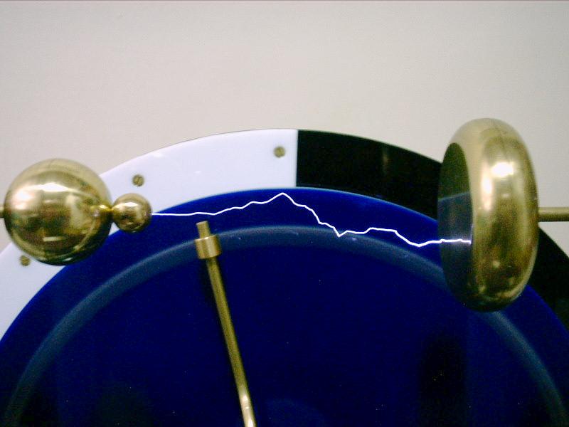
Bright sparks require intense current. The
current can be obtained by storing the charge extracted from the rotating
discs in high-voltage capacitors (Leyden jars) connected across the
machine terminals. The classical design comprises two Leyden jars with the
insulated terminals connected one to each terminal, and the outer
terminals interconnected. The spark gap usually consists of two metallic
balls connected by metal bars to the charge collectors. Significantly
longer sparks can be obtained by the addition of a smaller ball attached
to the positive terminal. This increases the electric field around the
positive terminal, forcing the ionization of the air to start at the
positive side of the gap, instead of at the negative side, as happens with
a symmetrical gap. The positive ionization forms a nice plume-like
structure (that can be seen in the dark) pointing away from the positive
terminal, that easily gets connected to the diffuse corona that the
negative terminal emits. When the connection is established, a spark
occurs, with the electrons flowing from the negative terminal to the
positive. Short sparks are observed as bright straight lines. Longer
sparks are more irregular, and may present branches, almost always in the
direction of the negative terminal. In short sparks, the positive end is
brighter, specially in sparks obtained without added Leyden jars, due to
more concentrated current. In long sparks, the positive end is always a
straight line perpendicular to the surface of the terminal, with the
negative side irregular and a little brighter (why is a mystery). When the
terminals are close to the maximum separation, "failed" sparks frequently
occur. The charges that the spark formation drains from the terminals
reduce the voltage between the terminals, and the spark is dissipated
before completion. Larger capacitance in the Leyden jars can extend
somewhat the maximum spark length, by providing more charge to complete
sparks that would "fail". The addition of a smaller ball to the negative
terminal is not effective. The electrons are ejected by the intense
electric field, and disperse quickly through the air instead of forming an
ionized path. This can be observed by a characteristic hissing noise. The
smaller ball doesn't need to be electrically connected to the main
positive terminal. It is still more effective if separated from the larger
ball by a short length of insulator (a short plastic tube, for example).
The small sparks between the larger ball and the smaller ball apparently
increase the ionization around the terminal, and the separation reduces
the loss of charge to the air (this I observed in my machines). In any
case, the longest sparks are obtained with the neutralizers at high angle.
Low angles increase the output current a bit [35].
Small balls can be added to both terminals, and in this case the longest
sparks are obtained with the positive terminal inclined
in the direction of the negative [35]. Another interesting gap structure
is the ball-plane gap, that replaces the
negative ball by a disk with rounded edges. This kind of gap requires less
voltage to produce a spark, and can produce very long sparks.
The terminal balls shall correspond to the
capabilities of the machine. A symmetrical gap with two spheres produces
sparks with up to about 4 times the diameter of the spheres. A ball-plane
gap goes to about 8 times the diameter of the sphere. Assuming that the
maximum spark length is approximately the sum of the distances between
adjacent sectors across a third of a disk, D,
the balls can be dimensioned based on this, with balls with diameter D/4 for a symmetrical gap and D/8 for a ball-plane gap. A double
ball gap can use this two sizes, maybe with the large ball larger. If the
small ball is insulated from the large ball, it can be even smaller than D/8.
The schematic above is from [68].
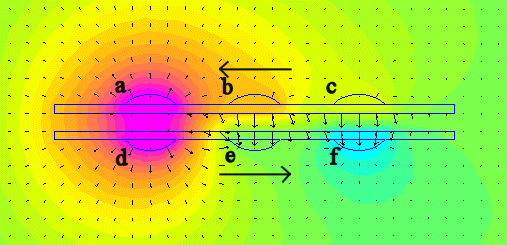
Simulations
The operation of the machine can be analyzed
quantitatively with the help of an electrostatic simulator. The simulation
result below shows an idealized section of the disks, with
three sectors in each disk, with the central sector e
touching a neutralizer brush. The simulated sectors are rectangular plates
with rounded surfaces, with 5 cm in length (direction perpendicular to the
plane), width of 1.5 cm and spacing of 1.5 cm. The disk plates have a
relative permittivity of 4, 0.25 cm of thickness and 0.5 cm of spacing.
The sectors a, b,
c, and d
are initialized with a total charge of +10 nC in each. The sector e
is grounded to 0 V (by a neutralizer brush), and sector f
, having already passed under the neutralizing brush, has a charge
identical to the charge in sector e.
A series of simulations is performed with the charge in sector f
varied until this condition is met. The simulation calculates the voltages
at the sectors as Va = 11 kV, Vb = 5.9 kV, Vc
= 3.0 kV, Vd = 11 kV, Ve
= 0 V, and V f= -3 kV. The
charge in sector e is found as
-14 nC. The arrows showing the directions and relative intensity of the
electric field show clearly that sector e
is influenced by sectors a, b, and d,
and this multiple influence is the cause of the charge gain of -1.4.
The machine can also be considered as a
network of variable capacitors and switches, with capacitances from the
sectors to ground and between all the pairs of sectors. The capacitances
between sector pairs in the same disk are significant only between
adjacent sectors. The capacitances between pairs of sectors in opposite
disks vary periodically in the time taken for a turn, becoming large when
they are facing each other and decreasing to practically zero when they
are at two sectors or more of angular distance. The other
capacitances, from sectors to ground and between adjacent sectors in a
disk, vary too, but in a first approximation they can be considered fixed.
The sectors are grounded periodically, in correspondence with the times
when they touch the neutralizers, twice per turn. The output circuit adds
another set of switches, connecting the sectors to the output at proper
times. This circuit model can be simulated in standard circuit simulators.
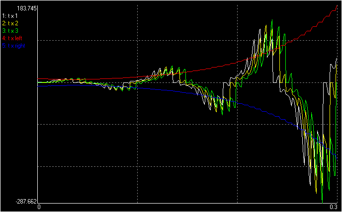
The picture below shows the result of a simulation of the startup of a
Wimshurst machine with 16 sectors per disk, turning at 10 turn/second. The
sectors are assumed to have 1 pF of capacitance to ground, 0.5 pF to
adjacent sectors, 5 pF to the opposite sector, and 2.5 pF to adjacent
sectors in the other disk. The voltages at three adjacent sectors and at
the two 100-pF Leyden jars can be seen. The initial excitation was
provided by ±10 V initially in the Leyden jars. In just three turns the
Leyden jars reach ±184 V.
Antonio C. M. de Queiroz
Created: 1996
Last update: 19 February 2018
Return to Electrostatic Machines