A double Voss electrostatic influence
machine
 The Voss machine, invented in 1880, is
a derivation of the Holtz and Toepler machines (1865), and so is also
known as the Toepler-Holtz machine (or even Toepler-Voss machine,
as Toepler also developed a similar machine by that time). This
design was very popular by the end of that century, being
extensively used for laboratory and medical applications,
including use as power supply for early X-Ray machines. It
consists of a fixed disk and a rotating disk, slightly smaller,
that rotates in front of it. At the back side of the fixed disk
are pasted two paper inductors with the shape of curved strips
covering an angle of about 90 degrees. These inductors are
connected to "appropriating brushes" that touch
metallic buttons in the rotating disk, as they start to cross the
region over the corresponding inductors. At the angle
corresponding to the other end of the inductors, a neutralizer
bar is positioned in front of the rotating disk. The bar has
brushes that touch the buttons in the rotating disk, surrounded
by combs with points, to act also on the rotating disk surface.
The output is taken by combs positioned horizontally in front of
the rotating disk, opposite to the inductors in the fixed disk (schematic). The design includes also
metallic strips under the paper inductors, terminated in two
disks, one in front of the corresponding appropriating brush,
connected to it by another strip, and other close to the other
end of the inductor (as here [18]). They turn the operation of the
machine less sensitive to the conductivity of the paper, that may
vary with the humidity level. The machine can be seen as a Holtz
machine, with the inductors charged from the buttons in the
rotating disk instead of from the back of the rotating disk, that
is not used, as in a Toepler machine, and with a set of round
metallic sectors that act as a starter for the machine, also as
in a Toepler machine.
The Voss machine, invented in 1880, is
a derivation of the Holtz and Toepler machines (1865), and so is also
known as the Toepler-Holtz machine (or even Toepler-Voss machine,
as Toepler also developed a similar machine by that time). This
design was very popular by the end of that century, being
extensively used for laboratory and medical applications,
including use as power supply for early X-Ray machines. It
consists of a fixed disk and a rotating disk, slightly smaller,
that rotates in front of it. At the back side of the fixed disk
are pasted two paper inductors with the shape of curved strips
covering an angle of about 90 degrees. These inductors are
connected to "appropriating brushes" that touch
metallic buttons in the rotating disk, as they start to cross the
region over the corresponding inductors. At the angle
corresponding to the other end of the inductors, a neutralizer
bar is positioned in front of the rotating disk. The bar has
brushes that touch the buttons in the rotating disk, surrounded
by combs with points, to act also on the rotating disk surface.
The output is taken by combs positioned horizontally in front of
the rotating disk, opposite to the inductors in the fixed disk (schematic). The design includes also
metallic strips under the paper inductors, terminated in two
disks, one in front of the corresponding appropriating brush,
connected to it by another strip, and other close to the other
end of the inductor (as here [18]). They turn the operation of the
machine less sensitive to the conductivity of the paper, that may
vary with the humidity level. The machine can be seen as a Holtz
machine, with the inductors charged from the buttons in the
rotating disk instead of from the back of the rotating disk, that
is not used, as in a Toepler machine, and with a set of round
metallic sectors that act as a starter for the machine, also as
in a Toepler machine.
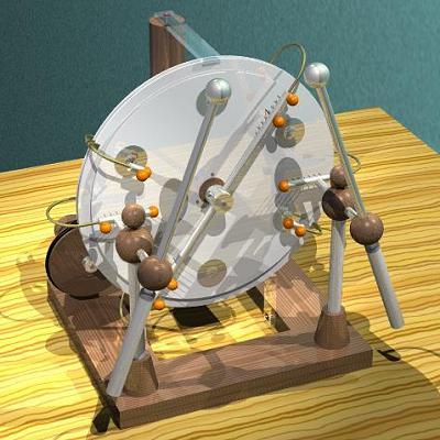
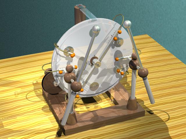
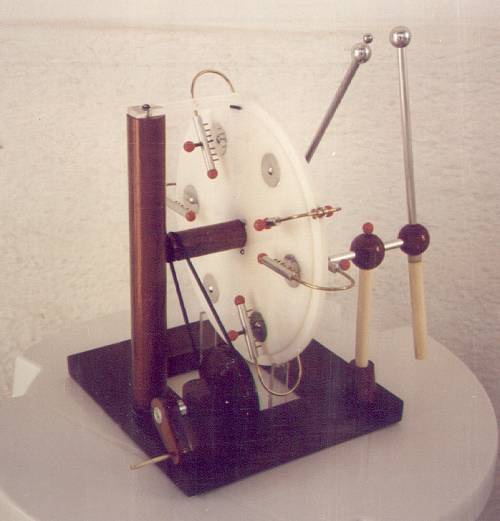
In June 1998 I completed a double Voss
machine. The machine has two of the basic machines connected
back-to-back, for greater output current and shielding of the
inductors, with shared driving system and terminals. It has a
wood support made of four bars with a cylindric upright support.
The two fixed acrylic disks have 30 cm of diameter, and are
supported by two acrylic pieces below and one above. They can be
rotated to any position, and their separation is of 5 mm. Each
has a set of two inductors, covering angles of 90 degrees and 5
cm wide, made of drawing paper, covering conventional metallic
strips and disks made of aluminum foil. The two rotating acrylic
disks have 27 cm of diameter and are mounted in a single wood
boss, screwed one at each side of a ring, part of the boss
between them, with three screws each. They turn at 2 mm of the
corresponding fixed disks. The boss has ball bearings fixed in
cavities at each extremity, that turn over a steel axis fixed to
the upright support. Each rotating disk has six round sectors
glued to it, with a button stamped in the middle, made of 0.4 mm
aluminum sheet. The neutralizers are fixed to the central axis,
so they can be rotated to any angle, and made with 9 mm aluminum
tubes, 1/8" brass bars that interconnect the combs/brushes
in the two basic machines, 1/16" brass wires for the comb
points, and brass pieces and screws to adapt the tubes to the
brass bars. The brushes were initially made of nickel-chrome
wire, but soon replaced by conductive rubber, that doesn't brake
easily with the repetitive contact with the buttons in the
sectors (the only problem is some startup difficulty in humid
days, comparing to the instantaneous startup with metal brushes).
The brushes are mounted at the end of screws that cross the
aluminum tubes, fixed to holes at their tips with wood pins and
glue, to allow some distance adjustment. The comb points are
simply glued to holes in the aluminum tubes. The charge
collectors and appropriating brushes are of similar construction.
All the extremities of the assembly are covered with 1 cm plastic
beads, or larger wood balls. The terminals are supported by
varnished 1.5 cm PVC tubes. Aluminum tubes connect the charge
collectors to the terminals, passing through wood balls mounted
over the insulating supports and fixed by screws from above. The
spark gap assemblies are connected to these tubes by slotted
brass plugs fixed to wood balls, so they can rotate with some
resistance. The spark gap rods are aluminum tubes that cross that
balls, and make contact with the plugs trough small springs
inside the wood balls. The terminal handles are also 1.5 cm PVC
tubes, adapted to the end of the tubes by nylon pieces, and the
terminal balls are in solid aluminum, turned on the lathe. The
machine is turned by a single pulley connected to a crank,
mounted in a support at the back side. All the wood parts are
varnished with several layers of polyurethane varnish.
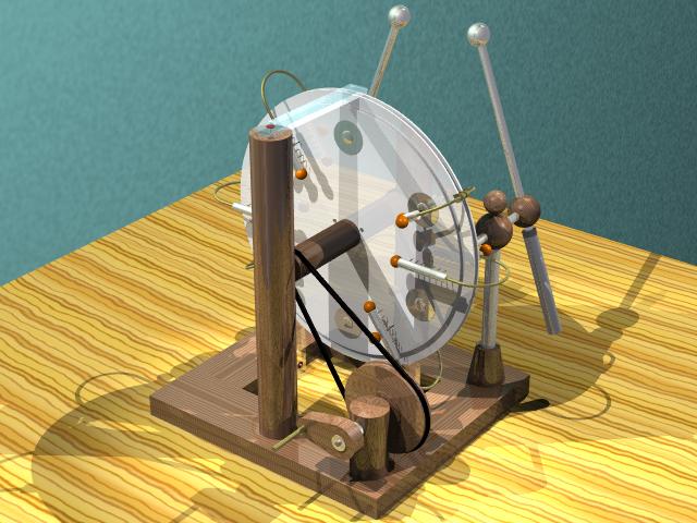
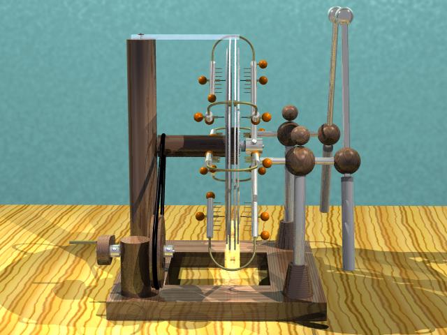
My machine can be seen in these ray-tracing drawings, in front view, back
view, and side view. Pictures from
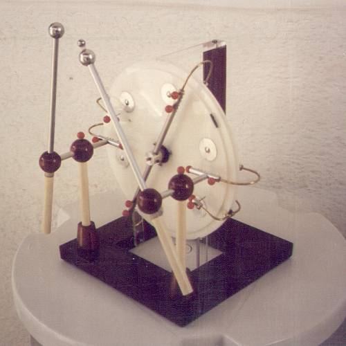
the machine, as initially built are here
(front) and here (back). The final
machine is seen here, with Leyden jars.
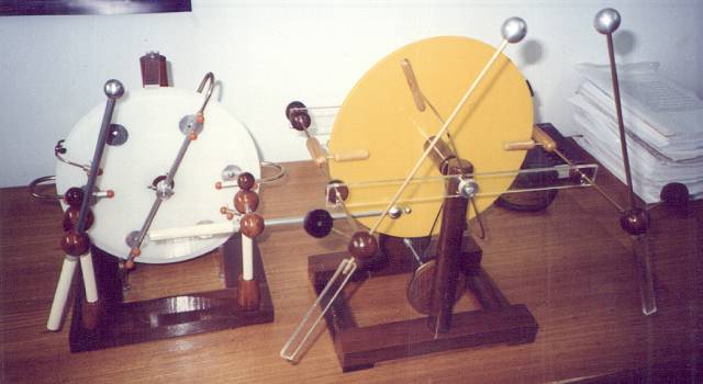
A picture of it used to excite my Bonetti
machine by placing one of the terminals in front of a
neutralizer, is shown here (this
single-point excitation works well only in dry air).
A similar, but maybe more beautiful, machine can be seen here [17] (with
the back fixed disk at a strange position). The configuration is
more clearly seen in this quadruple
machine [17].
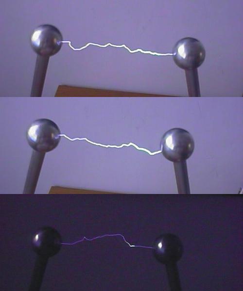
The machine self-excites easily, and in dry air produces
easily 6 cm sparks between 2.2 cm terminal balls, going to 9-10.5
cm with the addition of a smaller (9 mm) ball to the positive
terminal, and a pair of Leyden jars. In very dry air (as
conditioned air), even with the normal balls it goes to 10 cm sparks, and produces them easily
even with the disks moving slowly. The short-circuit current
reaches 60 uA with the disks turning at about 700 rpm. The
current is very high for a machine of this size, but the voltage
is just regular. In the dark, it is possible to see significant
leakage from the paper inductors to the bars that interconnect
the two sides of the neutralizer. Due to this, the highest
voltage is obtained with the neutralizer bar moved to a high
angle, somewhat away from the area covered by the inductors. In
this condition the machine takes some time to reach maximum
excitation, while charges spread from the inductors to the
surface of the fixed disks under the neutralizers. I added
plastic tubes enclosing the connections between the two sides,
with small improvement. A different design, without that
interconnection is something to experiment. Other leakage points
are the connections of the appropriating brushes to the
inductors, between pairs of inductors, and to the central boss.
The maximum possible spark length, given by twice the distance
between the active area of the disks and the central boss, would
be 11 cm. The machine shows significant resistance to polarity
reversal. Sometimes it reverts polarity after some time of
operation at high voltage, or if one pair of inductors is
grounded for some time while the rotation speed is reduced, or if
turned backwards for some time. The separation of inductors and
output avoids the polarity reversal at each spark, that happens
with my similar machines mounted with output and inductors
directly connected. The machine is significantly less prone to
reversals than the Holtz or Toepler machines. In dry air it is
even rather difficult to obtain a reversal, and the machine
performs as well as a Wimshurst machine, that does not revert
polarity while in operation.
The construction of the machine could be simplified, as there
is no need of two complete machines. One of the sides could have
a bare disk, no appropriating brushes, and no brushes at the
neutralizers, with the inductors connected to the inductors of
the other side. The complete duplication, however, turns easier
the self-excitation of the machine.
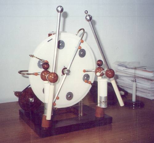
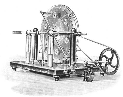
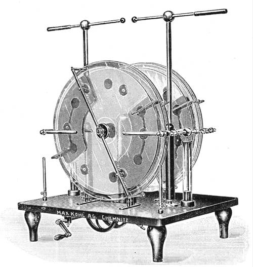
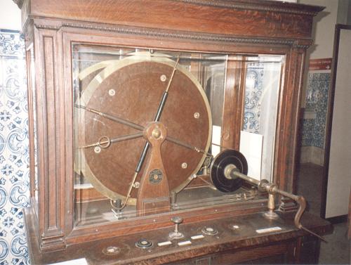
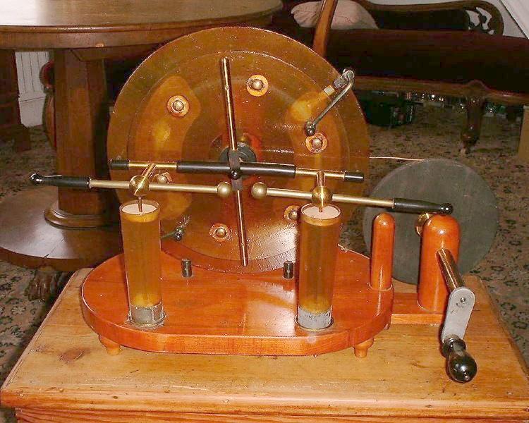
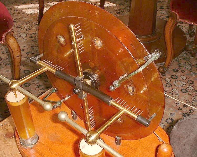
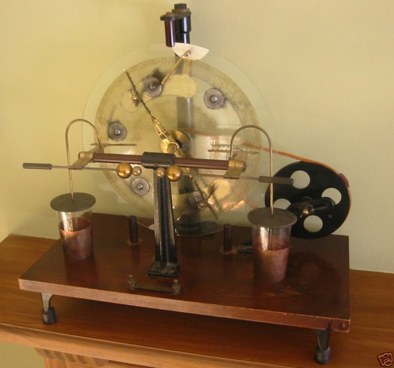
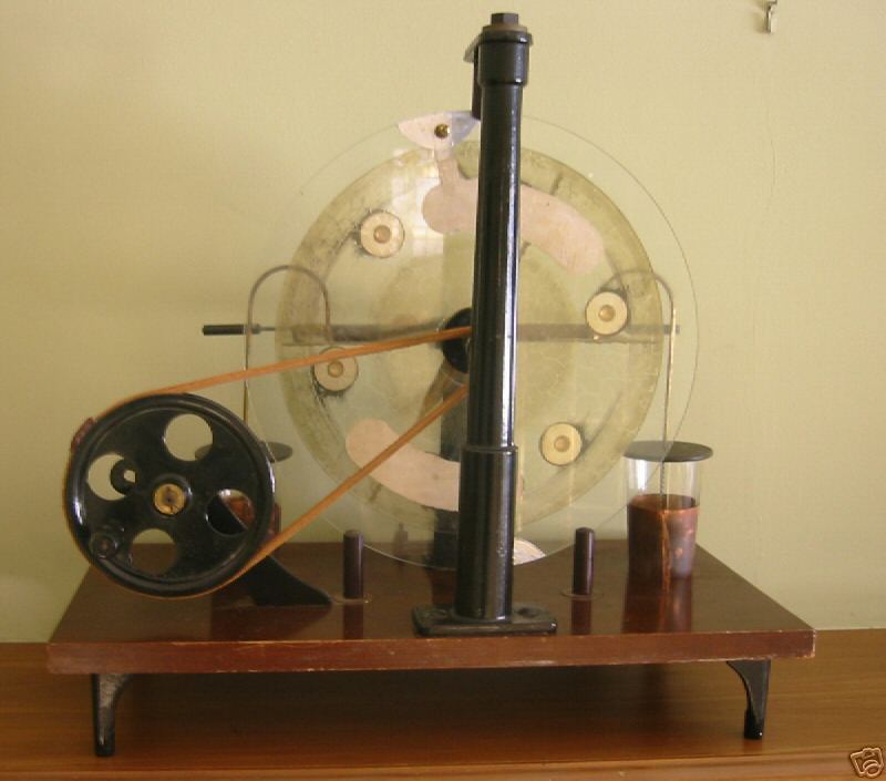
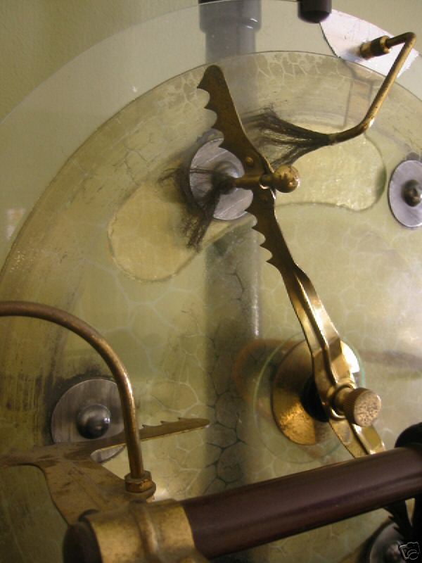
This picture shows an old double Voss
machine that is on display in a museum in Lisbon,
Portugal, that has interesting ideas. Note the assembly of the
appropriating brushes, mounted in supports at the frontal hub and
connected to the inductors by flexible wires. They have combs
covering the outer side of the charge transport area. One of the
output charge collectors is broken, and the output terminals are
missing. The rotating disks were made with a kind of mica
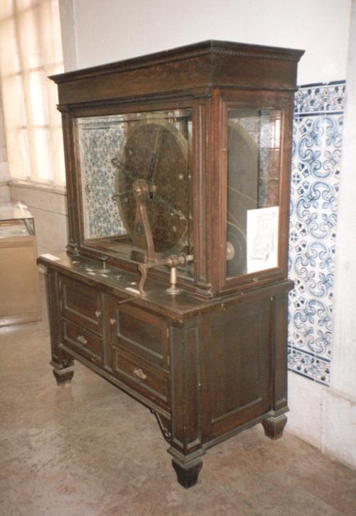
composite, and the inductor plates in glass. View of the cabinet. The machine is not quadruple. The
other set visible is a reflection in the glass. Note that there
are no buttons or brushes in the back disk, and that there are
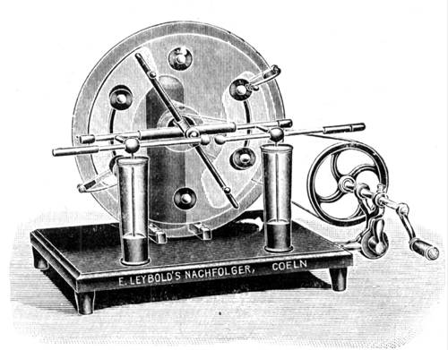
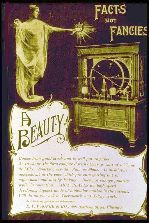
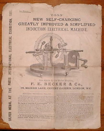
brushes in the frontal charge collectors (why?). An old advertisement of a very similar machine.
These large machines were common as power supplies for early
X-Ray apparatus.
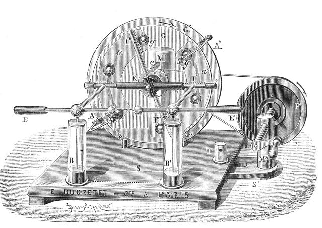
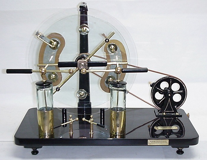
In July 2002, this apparently original
Voss machine, single, was being autioned at eBay. Another view, that shows details of the
construction, and part of a booklet
about it. The structure is as in this
drawing.
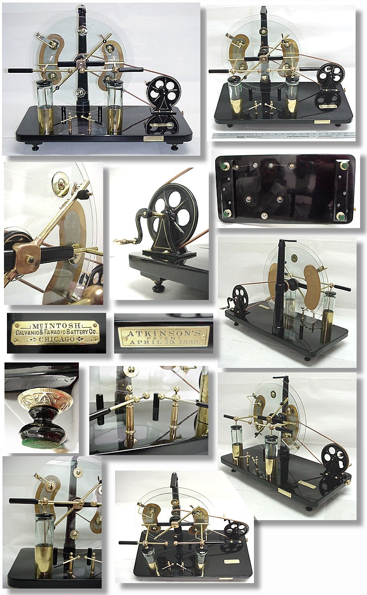
P. Atkinson [44] developed two
versions of the Voss machine. A restored single
machine with his design [US275347] patented in 1883 was auctioned in
eBay in 2000. More views of it. The
other was a double machine as mine, described in great detail in
his 1885 patent [US331754].
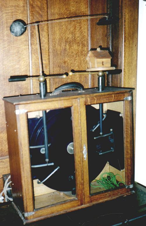
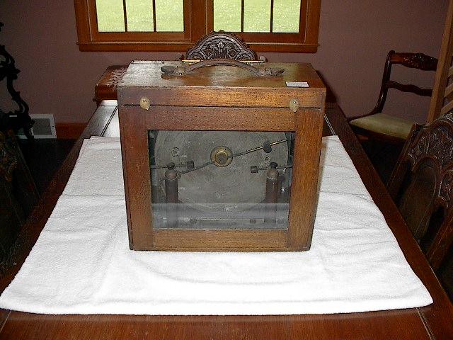
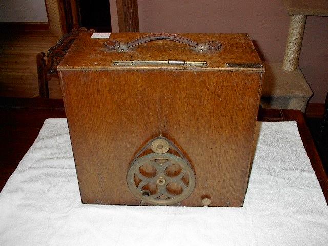
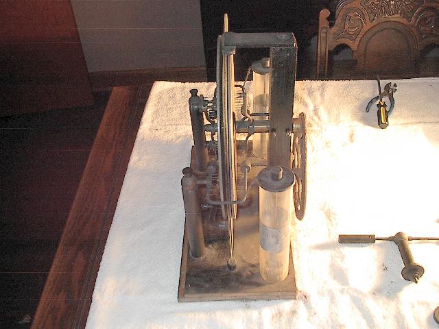
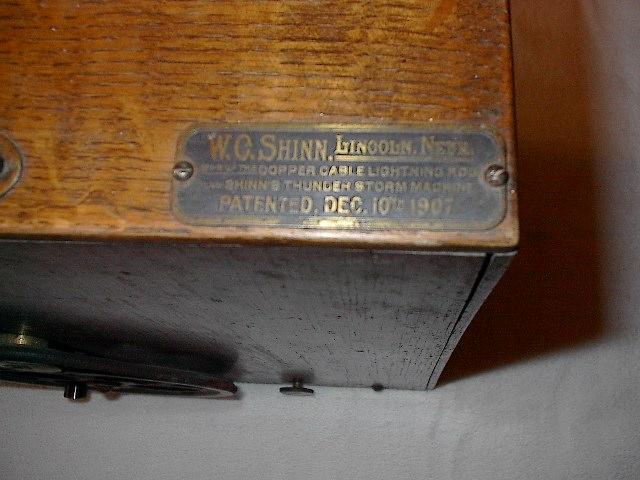
Voss machines were commonly used in the early 1900's for demonstrations of lightning rods. They were
characteristically mounted in a transportable box, having
attachments representing a "house" and a
"cloud", sometimes with also a "fence" and an
"animal". The machine in the picture appears to be
Baysdorfer's machine [US827497]
(1906). A single Voss machine is shown in [US700536] (1902). A double Voss machine
appears in [US837178]
(1907). Some pictures of a surviving machine of this type,
slightly damaged, were sent by Pete Windahl: Front view, back
view, with the box removed, and label. Another machine is shown in [US1043040] (1912).
By March 2005 a Voss machine was being auctioned in eBay. Front view, back view,
and detail. Note that the fixed disk
is incorrectly mounted. By the structure, this machine was built
in the 1900's.
Created: June 1998.
Last update: 10 March 2005
Created and maintained by Antonio Carlos M.
de Queiroz
Return to Electrostatic Machines