The electrostatic machine known as the Van de Graaff generator
was invented by Robert J. Van de Graaff, in the USA, by 1929,
with the objective of generating high voltages for experiments in
nuclear physics. It was first described in a short abstract in the Physical Review, vol. 38,
p. 1919, 1931, and in more detail in 1933 [p4].
The classical machine consists in a motorized insulating belt
that transports charge to a hollow terminal. Inside the terminal
the charge is collected by a row of points close to the belt and
transferred to the exterior surface of the terminal by the
Faraday "ice pail" effect. Charges are sprayed over the
belt surface by another row of points below, connected to an
electronic DC high-voltage supply. It is interesting to note that
the original machine was double, with two terminals oppositely
charged. More elaborated charging systems, as the use of current
doublers and self-excited operation were also considered in [p4].
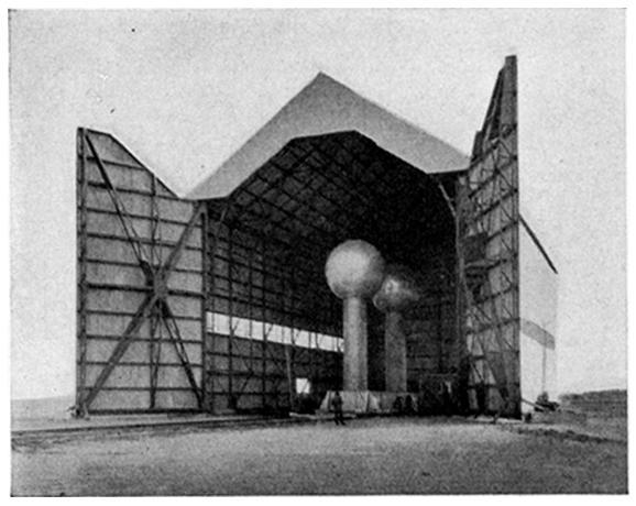
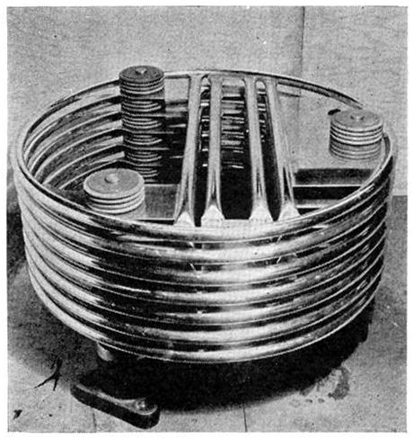
The machine was soon built in large scale as the Round
Hill electrostatic generator [p3], that
is now on display (mounted as
an unipolar machine [p5]) at the Boston Museum of
Science, in the USA.
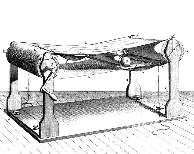
The basic ideas of the machine can be traced to the 1800's or
before, and particularly to Righi, who describes machines
using rubber tubes with metallic rings
[p55][p56] (1872) for charge transport with charge collectors
inside hollow terminals, and also double
tube machines and belt influence
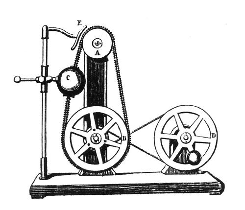
machines [p59] (1875). Another important antecessor is the Carré machine (1868), that uses a
charge
collector close to the terminal instead of inside it, a disk for
charge transport, and a friction machine as high voltage supply,
using influence to charge the disk from a grounded row of points.
Friction belt machines were known since the 1700's, as in the
machine made by Rouland by 1785 [50].
After the initial experiments with generators operating in
air, high-power Van de Graaff generators were built, operating in
tanks of compressed air, and later other gases, achieving several
megavolts of output voltage and much higher output current than
would be possible in the basic machine [p98].
An important improvement was the use of equipotential
rings along the insulating support and even along the belt
runs. The rings, biased at linearly varying voltages along the
support by strings of resistors or corona points, emulate a
supporting column with uniform resistivity and distribute evenly
the potential developed at the terminal. Machines of this type
continue to be used today, as power supplies for particle
accelerators [p100], X-ray
generators [p99],
and similar applications.
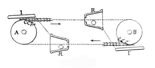
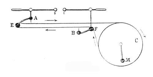
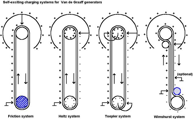
The excitation system for the machine can be built in many
ways. There is the original, and best, using an electronic
excitator to spray charge in the belt, and many other
possibilities, that can be identified with the charging systems
of the classic friction and influence machines. This picture shows some of the possibilities.
The friction system is very popular and simple, charging the
lower roller by rolling friction with the belt.The charged roller then
attracts opposite charge to the surface of the belt through a grounded
comb or brush. The performance
with this system is, however, quite impredictable. Other two
methods, that I call the Holtz and Toepler methods, adapt the
charging systems of their classic influence machines. Both
rollers are conductive and insulated, and the machine can produce any
polarity
at the terminal. In the Holtz system, the charges in the belt polarize
the rollers, and eventually leak to them, leaving then oppositely
charged. In the Toepler system, charges at the surface of the belt are
directly taken to charge them. The charged rollers then charge the belt
surface with opposite charges at each end through brushes or combs.The
systems that charge a roller with
charges
coming from the belt reaching it and use the charged roller as
inductor to charge the belt going away from it are called
"current doublers". Another system copies the charging
mechanism of the Wimshurst machine (actually one half of the
machine), or of the Holtz machine of the second kind. Each charged belt
run attracts opposite charges to the surface of the other, with a
reinforcing effect caused by electric field concentration at the combs
or brushes. This method
works well and is common in small laboratory machines.
The Van de Graaff generator is common in a variety of tabletop
models for demonstrations and experiments with electrostatics,
usually in unipolar configuration. Many descriptions of the most
usual systems can be found in the web. I decided to built a
machine that is not necessarily better, but is different from the
usual designs seen today and closer to the original machine.
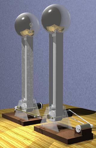
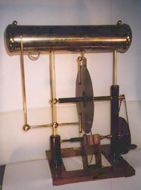
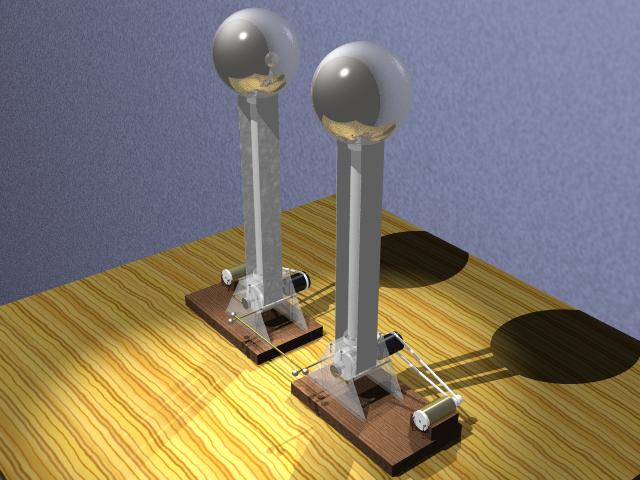
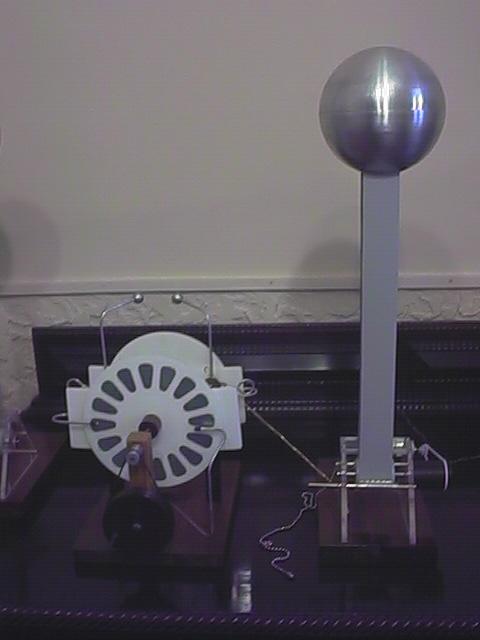
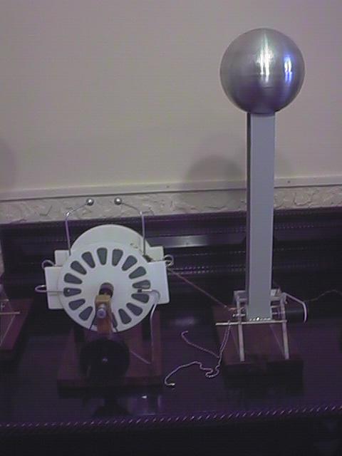
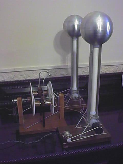
A double Van de Graaff machine:
In June 1999 I started to experiment
with a double Van de Graaff machine. A
double machine shall be able to produce greater potential
differences than an unipolar machine for a given terminal size,
because each terminal is charged to only one half of the total
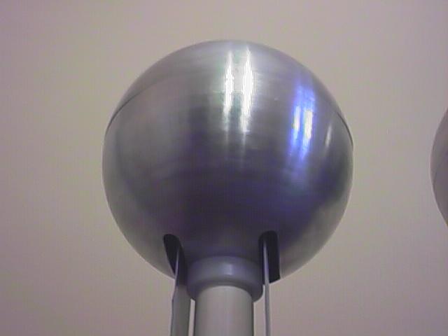
potential difference. My design uses two aluminum globes made by metal spinning, with 13.5 cm of diameter.
This is enough for 202.5 kV at each terminal (30 kV/cm of
radius), or more than 400 kV of potential difference.
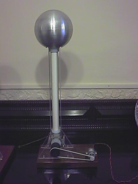
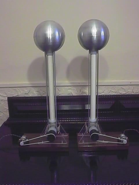
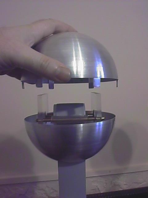
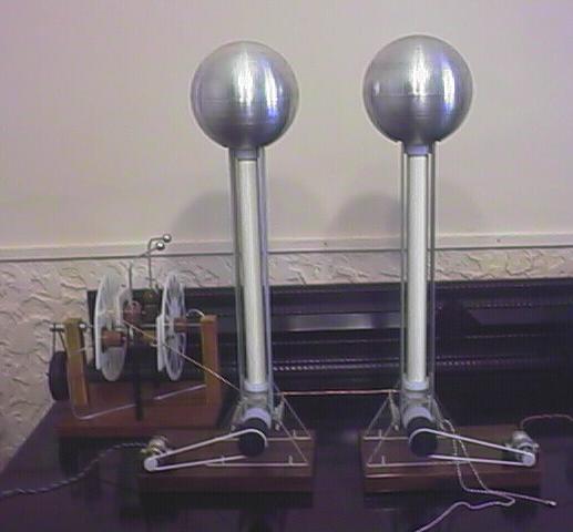
The complete machine is composed of two identical,
mirror-image units, that can be interconnected in several ways
that cause the machines to charge with opposite polarities. In
each unit, the terminal is mounted over a varnished PVC column,
with the belt running outside it. This allows easier access to
the belt, for observations, cleaning, and experiments, allows the
use of a wider belt for more charging current, and minimizes the
charge loss through the column, that has small diameter (1")
and the interior sealed. The tube can be removed from the nylon
plugs at its ends, what reduces the size of the machine for
storage, and removes the tension from the belt. There is an
evident problem of little insulation between the belt and the
terminal, but I wanted to see what would happen. The belt enters
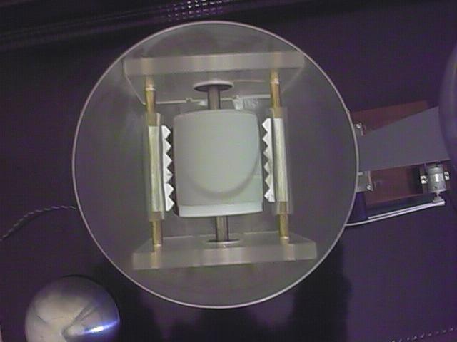
the terminal through two slits with rounded borders. Each unit
was initially assembled with identical current doublers below and
above (Toepler system), and in the absence of major losses should
be capable of sustained self-excited operation with any polarity
at the terminal.
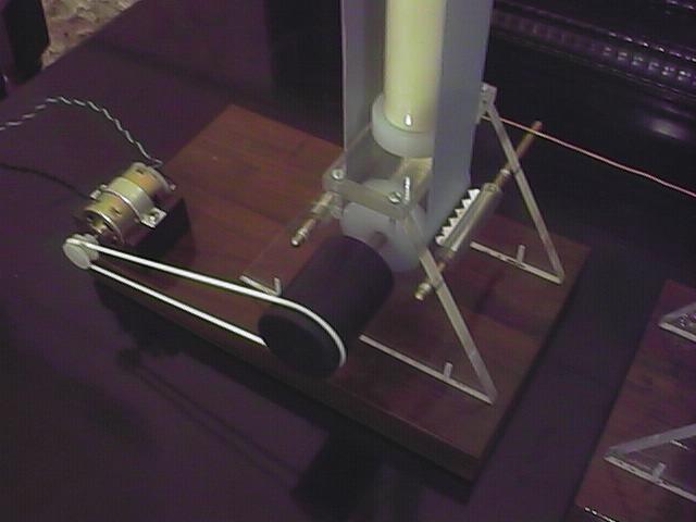
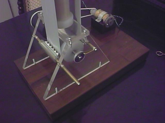
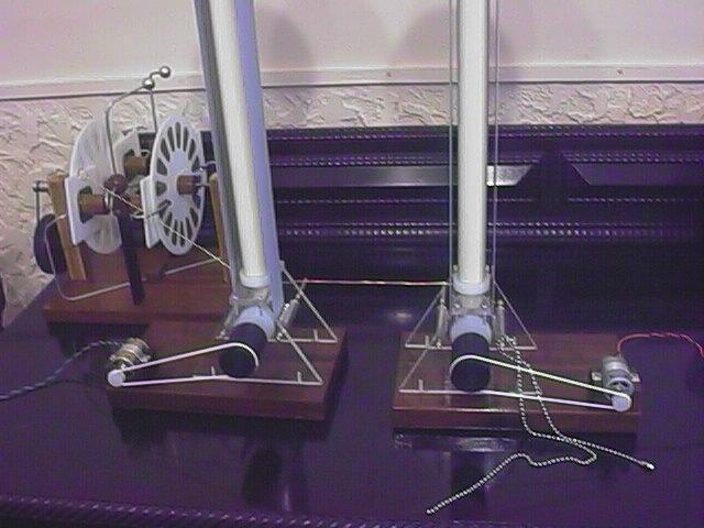
The upper and lower pulley assemblies, except for mounting
details, are identical. The pulleys were made in nylon with 4 cm
of diameter and 4.5 cm of length, and crowned by 1 degree angular
cuts at the outer 1.5 cm of each side. The centers of the pulleys
were covered by layers of adhesive aluminum foil, electrically
connected to the axles by pins passing through radial holes at
the centers of the pulleys. The pulleys were fixed by pressure
over 1/4" steel axles. The axles were supported by ball
bearings, fixed by pressure, that were glued in holes in the
acrylic supports. The same supports hold two charge collectors
each, one at each side of each pulley. One of the collectors, the
charging or doubler comb, is connected to the adjacent axle, and
the other, the spray comb, is connected in the lower assemblies
to an insulated bar, and in the upper assemblies to the
terminals. The charge collectors are made with serrated aluminum
foil wrapped over 3/16" brass bars and held in place by
plastic tubes that have a lengthwise cut. The lower pulleys are
driven by belt and pulley systems by 12 V DC motors, that can
move the belts at 3-5 turns per second. Electrical insulation is
provided by the use of large nylon pulleys. Speed is controlled
by varying the voltage applied to the motors. The belts have 4 cm
of width, and were made with a kind of gray latex material used
for physiotheraphic exercises (Thera band),
joined with cyanoacrylate glue in 45 degrees joints with 5 mm
overlaps. It appears that newer versions of this material, and several
similar materials, have an anti-static coating, turning them useless
for this purpose. In general, materials with something printed on them
shall be avoided. Pure
natural rubber, or latex, works well, and can be glued with "contact"
glue. The best way to glue the joint is to first glue both ends to
rigid plates (metal, plastic, etc.) with a weak glue at the sides
opposite to the ones to be glued. The rigid plates help in the precise
positioning
of the flexible belt material during the gluing procedure and can be
easily removed afterwards.
The units don't work reliably in self-excited influence mode,
apparently because the upper current doublers don't work, with
corona from the terminals at the slits canceling the charges that
would travel in the down-going belts. But the units get easily
charged to very high voltage if excited by a small electrostatic
machine. The excitation of a single unit can be by spraying
charge in the up-going belt with the lower pulley grounded, or by
charging the lower pulley and grounding the charging comb. A
single unit charged negatively can produce faint sparks to a
grounded object with about 15-20 cm of length. The charging
current was measured as 3-5 uA, what is consistent with the
theoretical expected value. When a terminal is positive, corona
plumes can be observed starting at the back of the up-going belt
and spreading out for about 10 cm or more below the terminal,
accompained by a cracking sound. A negative terminal is silent.
Both units can be excited to opposite polarities by charging
the lower pulley of one unit, interconnecting the lower spray
combs of both, and grounding the lower pulley of the other. It is
also possible to charge both lower pulleys with opposite
voltages, grounding both lower spray combs. There are other
possibilities too. It is difficult to obtain long sparks between
both terminals, despite the high voltage difference, unless a
small ball (3-4 cm) is attached to the positive terminal. This
results in sparks with up to 20 cm of length between the small
ball and the other terminal. Long sparks are faint, with the
appearance of a plume with the stem at the positive end, and only
visible in the dark, because the terminals alone don't store much
charge. High voltage Leyden jars attached to the terminals may
improve this, but it is not simple to attach jars to the
terminals without introducing significant losses at that very
high voltage. A single unit can easily make all my current jars
spark over. Long discharges between the normal terminals take the
form of curious faint plumes that make a curve below the
terminals, sometimes touching part of the up-going belts. These
discharges, probably starting at the belts and entry slits,
discharge the terminals preventing direct long sparks between
them.
An impressive experiment with Leyden jars: With a positive
terminal, long corona plumes appear below the terminal. A small
Leyden jar held by its outer plate and with the terminal close to
these plumes, maybe 10 cm away from the terminal or more, gets
quickly charged to more voltage that it can sustain, and sparks
over (terminal to border of outer foil) with a violent spark,
while held in the hand. The operator doesn't receive any shock.
Improving the machine
In May 2002, I replaced two of the
rollers by Teflon rollers, below in one unit and inside the
terminal in the other. I also increased a bit the crowning of the
pulleys with 2 degrees cuts, increased the tension in the belts,
and used a better power supply for the motors. With this I
obtained two units that work reliably using excitation by rolling
friction. The Teflon rollers become negatively charged, and so
the unit with the Teflon roller below generates positive charge
at the terminal, and the other unit generates negative charge. I
kept the current doublers, even with the Teflon rollers. The
units generate similar voltages and charge with the same current.
Both units operate interconnected through the lower spray combs,
that can be grounded or floating with identical results.
The negative unit gets charged first and works a bit better,
possibly due to smaller losses. It also works better with the
comb in the lower current doubler disconnected. Apparently, the
poor insulation of the nylon roller used in the doubler causes
losses by currents that discharge the roller through the path
roller - doubler comb - nylon surface of the roller - spray comb.
With the comb disconnected the doubler works by the Holtz system,
with smaller losses because a current discharging the roller
metal surface would have to track under the belt to reach the
exposed nylon surface and the spray comb. The current doubler on
this unit evidently works, and most of the charging current comes
from it. The machine practically stops if the lower pulley is
grounded. The pulley must be well insulated, with the support and
specially the insulating pulley driven by the motor clean and
dry.
The positive unit (left) shows a curious phenomenon. It
charges slowly at first, but after some time suddenly charges to
the maximum voltage and keeps it. A possible cause is the
operation of the current doubler mounted in the Teflon roller
below, that starts to operate, even with an insulating roller,
after the voltage gets high enough. The connection or not of the
doubler comb inside the terminal doesn't have any observable
effect.
The units produce faint sparks between the terminals with up
to 20 cm with the help of a small ball attached to the positive
terminal, and up to 9 cm sparks, more visible, directly (~180 kV
of voltage difference). With greater spacings corona bursts are
seen between the slits where the belts enter the terminals. This
is the same behavior of the original machine.
Energy in a Van de Graaff generator:
Many people don't realize that these machines can produce
dangerous shocks. The danger of an impulsive shock is
proportional to the energy that it discharges, with about 10
Joules of energy being considered dangerous [10].
The energy stored at the terminal of a Van de Graaff generator
can be calculated as E= 0.5CV2,
where C is the distributed capacitance of the terminal and V its
voltage relative to ground. The capacitance of a sphere is given
by C = 4pe0r, where e0 = 8.85x10⁻¹² and r
is the radius of the sphere (meters), resulting in C = 111.2r pF.
The maximum voltage that the machine can produce is limited by
the electric field E at the surface of the terminal. For a
sphere, voltage and electric field are associated by V = Er.
Assuming the maximum electric field in air as Emax = 3
MV/m, V = 3x10⁶r. Combining these expressions, the
stored energy is obtained as E = 500.4r3.
E = 10 J would then correspond to r =
0.27 m. A machine with a terminal larger than this, and small
losses, would be dangerous, with the danger increasing rapidly,
with the cube of the radius.
With r = 6.75 cm, One terminal of my machine stores at most
0.1539 J. Enough for unconfortable shocks, but not dangerous.
Required mechanical power and charging current:
An estimation of the required mechanical power to move the
charged belt, to be added to the power required to move the
uncharged belt, is simply P = VI, where V is the terminal voltage
and I is the belt current. Assuming the belt operating at the maximum charge density and transporting
current upwards only, I = e0EmaxWv,
where W is the effectively used belt width and v is the belt
speed. Considering that the maximum terminal voltage is V=Emaxr,
P = e0Emax2rWv.
For a driving pulley with diameter d, turned at a
rotations per minute (rpm), v = (a/60)pd,
resulting in P = e0Emax2(p/60)rWda. The charging current is
I = e0Emax(p/60)Wda.
Note that the power is proportional to the cube of the
"size" of the machine, the voltage is proportional to
the size, and the current is proportional to the square of the
size, if the proportions and the motor speed are retained. This
happens with all electrostatic machines.
The length of the belt, or the height of the terminal, have no
influence if the motor speed is constant (except for insulation,
and a small effect on the output voltage, not considered). The
length L appears in the formula for the current in the form I = e0EmaxWLn, where n is
the number of belt turns per second. The power is then P = e0Emax2rWLn
For my machines, ignoring the doublers, with r = 0.0675 m, W =
0.034 m, L = 0.969 m, and n = 4, the predictions are I = 3.5 uA
and P = 709 mW
The current agrees precisely with measurements. The power is
difficult to evaluate, since the mechanical losses are large, the
maximum voltage is not reached, and some power is spent to
separate the belt from the charged rollers. In a single unit (the
positive), the measured input power for the motor, with 6 V and
0.64 A, is 3.84 W. With the terminal uncharged and the lower
spray comb disconnected (no charging current), the current
decreases to 0.59 A and the power decreases to 3.54 W, indicating
a difference of 300 mW. The terminal sparks to the grounded
terminal of the other unit with 4 cm sparks, what corresponds to
about 100 kV of voltage, corresponding to 350 mW of predicted
input power. Close to the measured value, given the uncertainties
of the measurements.
Comparison with other machines:
In comparison with other electrostatic machines operating in
air, it's certain that for the production of very high voltages
the Van de Graaff machine is the logical choice. But this is not
so if all that is wanted is a convenient power supply for
experiments with electrostatics or a machine that can produce
long sparks. In comparison with most of the classical disk
machines, a motorized VDG machine is noisy and mechanically
problematic, the generated current is very small, the charge
stored in the terminal is insufficient for long solid sparks, the
output is unipolar, and the structure is inconvenient for
connection to other devices. A disk machine as a triplex
Wimshurst or a Bonetti machine with
similar size can
easily produce equivalent voltages (if sufficiently insulated), at both
polarities, at much
higher current.
 In June 1999 I started to experiment
with a double Van de Graaff machine. A
double machine shall be able to produce greater potential
differences than an unipolar machine for a given terminal size,
because each terminal is charged to only one half of the total
potential difference. My design uses two aluminum globes made by metal spinning, with 13.5 cm of diameter.
This is enough for 202.5 kV at each terminal (30 kV/cm of
radius), or more than 400 kV of potential difference.
In June 1999 I started to experiment
with a double Van de Graaff machine. A
double machine shall be able to produce greater potential
differences than an unipolar machine for a given terminal size,
because each terminal is charged to only one half of the total
potential difference. My design uses two aluminum globes made by metal spinning, with 13.5 cm of diameter.
This is enough for 202.5 kV at each terminal (30 kV/cm of
radius), or more than 400 kV of potential difference.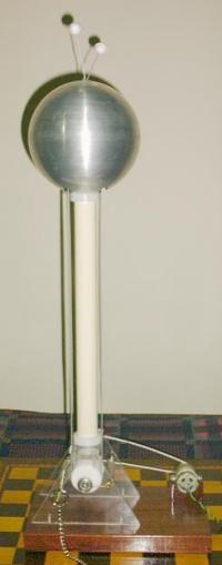 In May 2002, I replaced two of the
rollers by Teflon rollers, below in one unit and inside the
terminal in the other. I also increased a bit the crowning of the
pulleys with 2 degrees cuts, increased the tension in the belts,
and used a better power supply for the motors. With this I
obtained two units that work reliably using excitation by rolling
friction. The Teflon rollers become negatively charged, and so
the unit with the Teflon roller below generates positive charge
at the terminal, and the other unit generates negative charge. I
kept the current doublers, even with the Teflon rollers. The
units generate similar voltages and charge with the same current.
Both units operate interconnected through the lower spray combs,
that can be grounded or floating with identical results.
In May 2002, I replaced two of the
rollers by Teflon rollers, below in one unit and inside the
terminal in the other. I also increased a bit the crowning of the
pulleys with 2 degrees cuts, increased the tension in the belts,
and used a better power supply for the motors. With this I
obtained two units that work reliably using excitation by rolling
friction. The Teflon rollers become negatively charged, and so
the unit with the Teflon roller below generates positive charge
at the terminal, and the other unit generates negative charge. I
kept the current doublers, even with the Teflon rollers. The
units generate similar voltages and charge with the same current.
Both units operate interconnected through the lower spray combs,
that can be grounded or floating with identical results. 