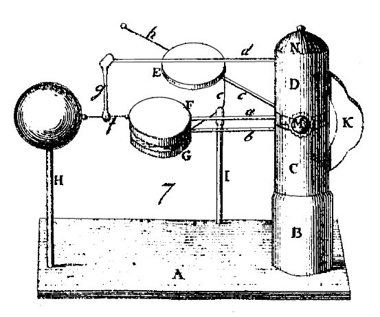
This is another of the doublers described in 1801 [p107] by Gottlieb Christoph Bohnenberger, in a summary of the same subject contained in his book [55] from 1798. This machine operates exactly as Nicholson's doubler, but has a back-and-forth movement instead of a rotating movement.
Three conductive disks E, F, and G, are mounted on insulating rods a, b, and c, fixed to the wooden support structure. The support has a fixed base B, with a central metal axle inserted on it. On this axle, the cylinders C and D can rotate freely. A central short cylinder is fixed in position by the screw M. A piece N is fixed at the top to cover the end of the axle. A wire e, supported by the insulating rod I, puts in contact the disks E and G in the position shown. A wire h is fixed on the disk E, and touches the large metal ball supported by the insulating rod H when the assembly is rotated counterclockwise. A wire f puts the central disk F in contact with the ball. This wire is supported by the rod h and the insulating rod d, and turns along with the cylinder D and the disk E.
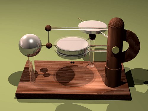
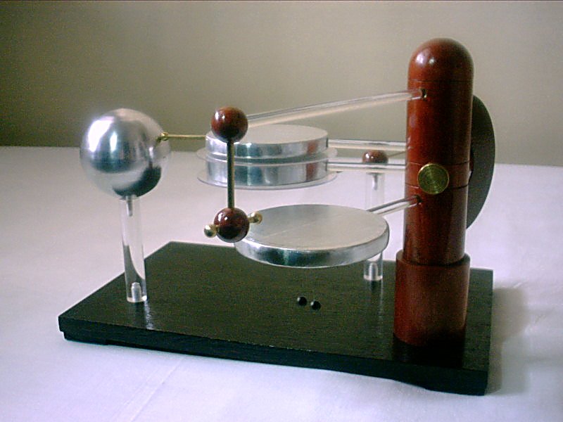
The rendering below shows my plans for this machine. I used acrylic rods, wood disks, leveled and polished, covered with adhesive aluminum foil, and 1/8" brass rods for the contact wires, ended in 1/4" brass balls. I added two spark shields glued to the central disk to increase the maximum voltage that the device can generate. The shields were made from disks cut from CD boxes. The disks have a diameter of 8 cm. The electroscope was made with two 5 mm styrofoam balls painted with conductive ink (China ink), and suspended through thin metal wires ended in rings from a wire ring fixed below the lower plate G. The large aluminum ball is hollow and was made by metal spinning.
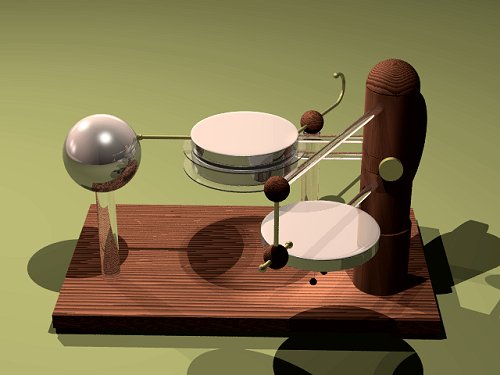
To operate the machine, the handle K is moved back and forth, rotating the upper and lower disks in an angle of about 60 degrees. At the extreme rotation to the right side (above), the upper disk is in contact with the lower disk through wire e, and the central disk is connected to the large ball by the wire f. This connection concentrates the charges that were in the upper and lower disks in the lower disk, makes an inverted copy of the charge in the central disk, an pushes an opposite copy of the charge to the ball.
At the other extreme of the movement (above), the upper disk
is in contact with the ball through the wire h.
A copy of the charge in the central disk, inverted, is pulled
from the ball to the upper disk. The charge coming from the ball
is ideally the same pushed to it in the previous step. The lower
disk is far from the others, and if there is enough charge on it,
the electroscope balls show its presence.
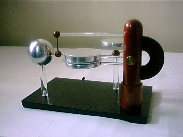
Each cycle approximately doubles the charges in the lower and central disks, until a spark between the disks discharges the machine, or leakage through corona limits the voltage. The saturation is usually reached in 10-20 cycles, starting from discharged disks. This machine, although using practically the same dimensions of the elements used in my construction of Bohnenberger's Bennet's doubler, appears to be somewhat weaker, but this may be a consequence of the position of the electroscope. Differences in the distances between the disks cause the large ball to accumulate charge, what may be prejudicial to the operation, but grounding the ball (transforming the machine in Bennet's doubler) doesn't make great difference. This machine is difficult to adjust precisely, ensuring good contacts between the wires, the disks, and the ball. It would be better to use flexible contacts instead of the little balls that I have used.
The actual machine in the copy position.
Created: 21 July 2004
Last update: 6 April 2012
Developed and maintained by Antonio Carlos
M. de Queiroz.
Return to Electrostatic Machines