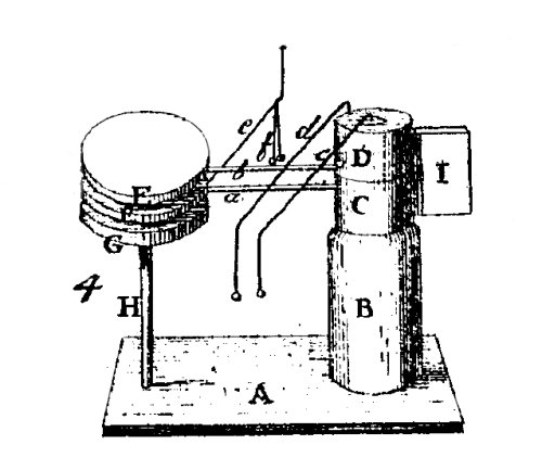
In a paper published in the "Annalen der Physik" in 1801 [p107], the German scientist and preacher Gottlieb Christoph Bohnenberger described a curious little electrostatic machine, based on the operation of Bennet's doubler.
The three wooden disks covered with metal foil E, F, and G, are supported by the insulating glass rods a, b, and H. The rods a and b are fixed in the cylindrical wood blocks D and C, that can rotate around a pin mounted above the wooden column B. The handle I is fixed to the block D, and has a cut at the lower part of its back side, where a smaller handle K (hidden in the picture) fixed to block C stays, when the device is as in the figure. The wires c, d, and e, terminated in small balls or rings, make the role of the contacts and touchings with the fingers in Bennet's doubler. The wire c is fixed to the pin above the column B, and makes contact with the upper disk E when it is fully rotated to the left (counterclockwise). The wire d is fixed to the block D, and makes contact with the central disk F when the disk E is fully rotated to the right (clockwise). The wire e is fixed to the lower disk G, and makes contact with the upper disk E when it is fully rotated to the right. The column B and the glass rod H are mounted over the wood base A. f is a ball electroscope suspended from the wire e to allow visualization of the output voltage.
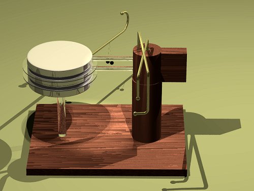
The rendering above shows my plans for a similar machine. I used acrylic rods for better insulation, wood disks, leveled and polished, covered with adhesive aluminum foil, and 1/8" brass rods for the contact wires. I added two spark shields glued to the central disk to increase the maximum voltage that the device can generate. The shields, made from disks cut from CD boxes, required curves in the wires e and d. The disks have a diameter of 8 cm. The electroscope was made with two 5 mm styrofoam balls painted with conductive ink (China ink), and suspended through thin metal wires ended in rings from a thin wire ring around wire e.
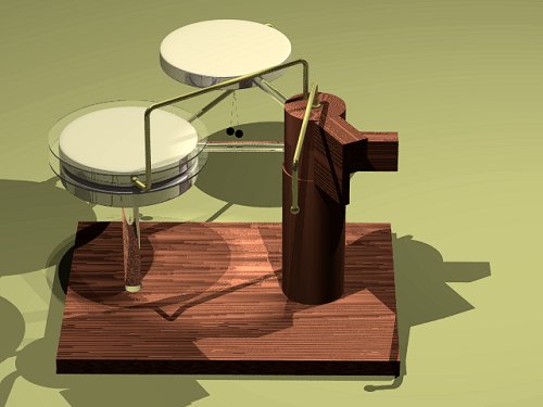
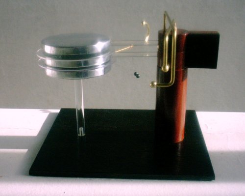
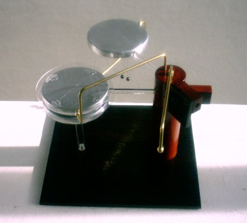
To operate the machine, the handle I is moved back and forth, rotating the upper disk in an angle of about 120 degrees. At the extreme rotation to the right side (above), the upper disk is in contact with the lower disk through wire e, and the central disk is grounded by wire d. The wire d can be used to push the central disk to the right position above the lower disk. This connection concentrates the charges that were in the upper and lower disks in the lower disk, and makes an inverted copy of the charge in the central disk.
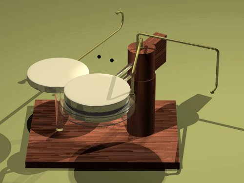
When the upper disk is rotated to the left, the handle I catches the handle K of block C and both the upper and central disks rotate together until the upper disk contacts wire c (above). This makes a copy of the charge in the central disk in the upper disk. When the upper disk is rotated to the left again, this charge is added to the charge in the lower disk, completing the doubling operation. Each cycle approximately doubles the charges in the lower and central disks, until a spark between the disks discharges the machine, or leakage through corona limits the voltage. The spark shields impede the discharge by sparks, but leakage, specially at the electroscope, limits the maximum voltage attainable at about 5 kV. The saturation is usually reached in 10-20 cycles, starting from discharged disks. At the maximum voltage, small sparks can be heard when the disks contact the wires. A machine with about twice larger disks would produce clearly visible sparks.
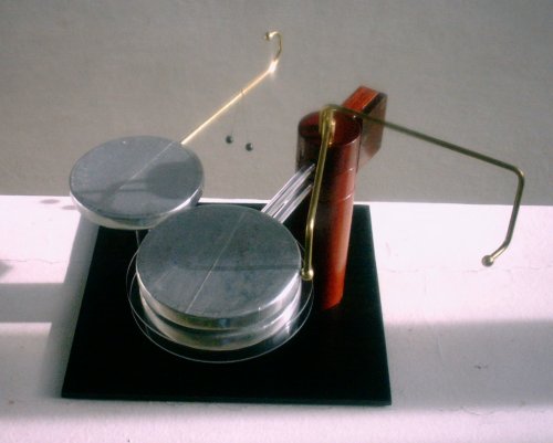
The actual machine. Doubling position. Copy position.
A movie
or the
rendered machine in operation. In this case showing the operation
mode described by Bohnenberger. If the rotating wire d
is used to push the central disk the operation is simpler, and
there is some extra rising in the voltage at the lower disk when
the upper disk passes above it. Video on Youtube.
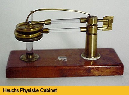
A very similar machine, apparently the same with the wire c missing, can be found here.
Created: 16 April 2004
Last update: 13 November 2011
Developed and maintained by Antonio Carlos
M. de Queiroz.
Return to Electrostatic Machines