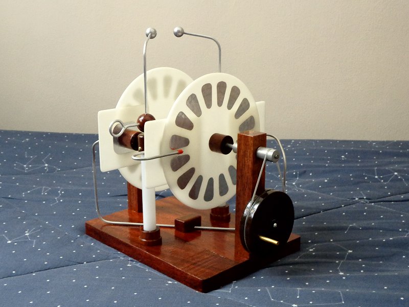
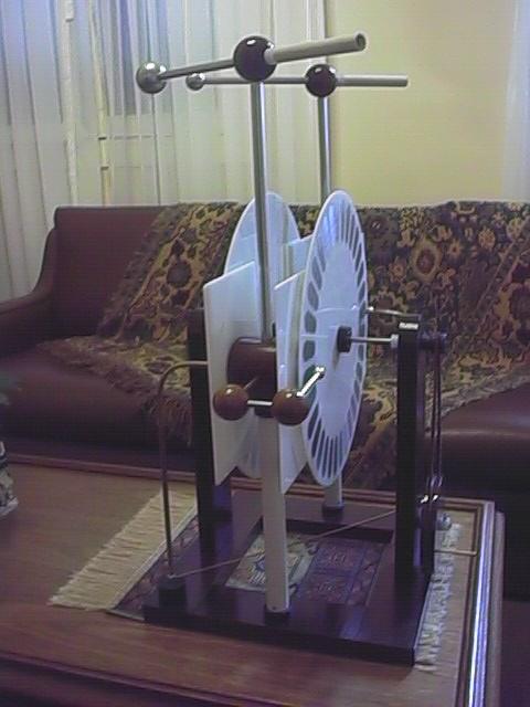
The machine in January 2015
The main limitation on the voltage attainable in the Voss machine, or in any machine with diagonal neutralizers, is that sparks can jump between the charge collectors through some disk sectors and the neutralizer bar. This limits the maximum spark length to about the sum of the inter-sector distances across 1/4 to 1/3 of the rotating disk. (A little more, because as voltage is not linearly proportional to spark length, it is easier to form a spark across a large gap than across a series of small gaps adding to the same distance.)
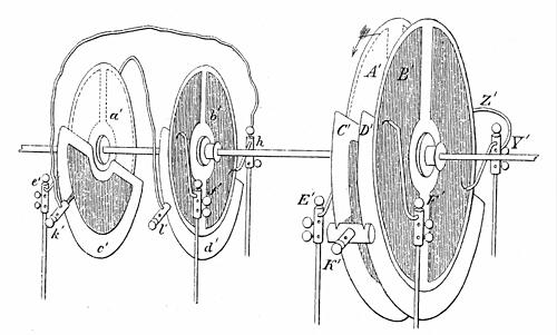
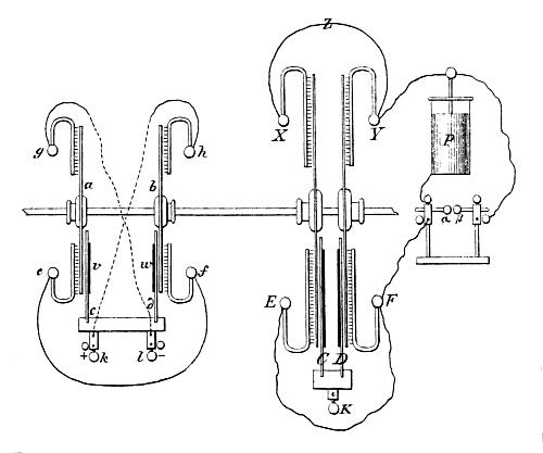
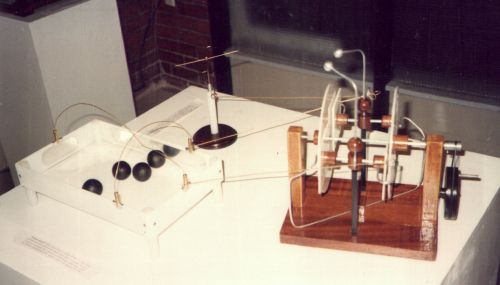
A machine that works in the same way but doesn't present this limitation can be built by splitting the rotating disk in two, rotating in the same direction or not, and adding two assemblies that collect charge in one disk and induce opposite charge in the other disk. These assemblies work as the inductor plates in a (simplified) Voss machine, but have brushes collecting charge from one disk and inductor plates inducing charge in the other. A single neutralizer wire with brushes touches the sectors in the two rotating disks when they are in front of the inductor plates. Based on this idea, I built a machine in 1997, that later I found to be similar to a machine described by August Toepler in 1866 [p39], in a paper comparing the performance of sectorless and sectored machines, in this configuration (the device at the right in the pictures is a "continuous electrophorus" that can be connected to the output of the machine and allow the generation of many sparks without discharging the main machine).
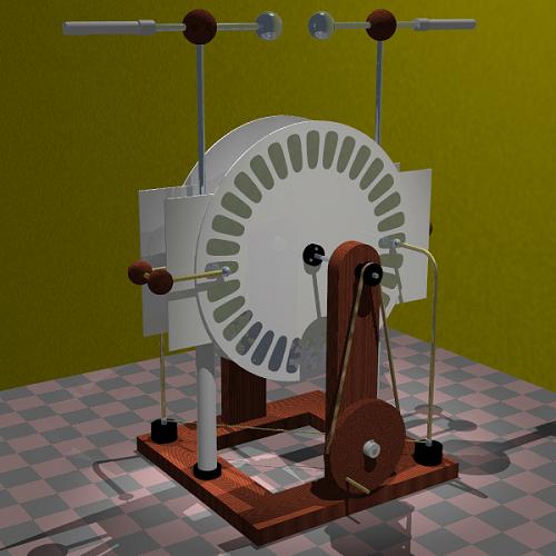
I used more effective charge collectors and Wimshurst-style disks. The structure increases the maximum spark length to about the sum of the inter-sector distances in an entire disk, or twice the distance between opposite sectors in a disk (if the disk centers are insulated one from the other), or to the double of the distance between the sectors and the disk bosses, with the disks mounted in a single metallic axis, as in the machine that I built to test the idea. Without special insulation, the distance between opposite charge collectors and inductors limits the highest spark length to about the last value.
This machine also shows some curious properties, as that the disks can turn in any direction, and that the polarity of the charges in a disk is always practically the same (a small reversal can occur). The problem of polarity reversals occurs also in this machine, as in all machines with fixed inductors. With the output taken directly from the collector/inductors, at each large spark the machine polarity is reversed due to charges stored in the opposite sides of the inductor plates and the disks. Without Leyden jars, however, the output polarity is quite stable, but can be reverted easily by touching one of the terminals.
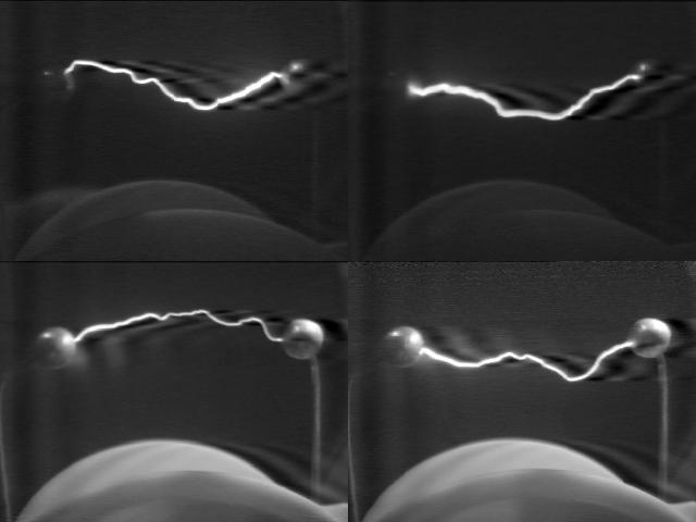
My machine, with 17 cm disks, produces sparks with up to 7 cm, what is precisely twice the distance between the sectors and the disk bosses. If the same disks were used for a Wimshurst machine, sparks with 4 cm would be obtained, at most.
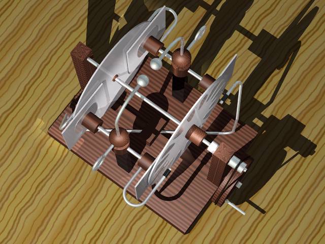
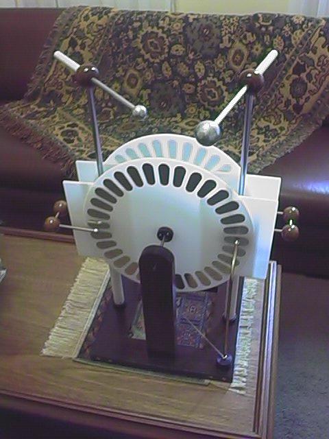
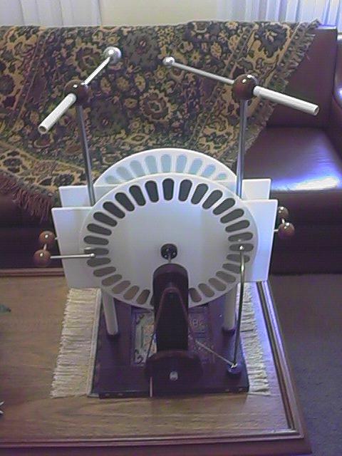
The machine is composed of two acrylic disks 2.5 mm thick, each with 16 sectors made of aluminum foil (from a discardable pizza base) glued with a contact glue to the disks. The disks are mounted (glued) in wood bosses and turn in a steel axle (just fixed by pressure) that runs on ball bearings mounted in two wood posts. At one end of the axle there is a small aluminum pulley, that is turned by a larger wood pulley below, by a crank mounted in the pulley. The large pulley runs in a partial machine screw fixed in a hole in the support. Screws in the aluminum pulley and in another small aluminum piece fix the axle in place.
The two collector/inductor assemblies are composed by horizontal steel bars connecting two aluminum foil inductors glued to square acrylic plates, that are held in position at about 1 mm of the rotating disks. One of the plates in each assembly is connected to a brush that touches the sectors in the opposite side of a disk, through a U section of thick aluminum wire. The assemblies are mounted in insulating acrylic supports, in centrally symmetrical positions, and have at the center aluminum bars that support the terminals. The connections are made of wood cylinders and balls, with small springs inside holes connecting the metallic parts, that are attached to the wood blocks by pressure.
The distance between the disks and the collector/inductors assemblies can be varied a few mm by sliding the disk bosses in the axle. The terminals are two aluminum balls with 1.4 cm of diameter, and there are also supports for Leyden jars and other connections. The terminal supports can be rotated in the vertical axis to change the spark gap length. The neutralizer wire is made of aluminum wire fixed at the center of the machine base. The brushes are made of fine nickel-chrome wire taken from a wire-wound resistor, and touch very lightly the disks (just 2 wires per brush). They are held in place by sections of wire insulation inserted in the aluminum wires. I tried also carbon fiber brushes, taken from a discarded laser printer, with success. All the wood parts are polished and varnished with polyurethane varnish.
Note that this machine can be easily constructed with cylinders instead of disks. Two groups of sectors can be fixed close to the opposite ends of a single rotating tube, in the inner side, and the collectors/inductors can be simple metalic strips fixed to the outer side of an outer, fixed, cylinder. Four brushes touching the inside of the inner cylinder and connections complete the machine. This is just a slight variation of the structure of my cylindric simplified Voss machine.
And made with disks or cylinders, the machine can be built sectorless, with the brushes replaced by combs with points close to the rotating surfaces, what can further increase the maximum voltage attainable.
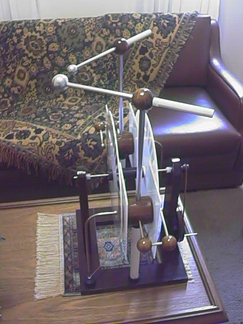
A picture of it in an exposition, driving an electric wind spinner and an "electric soccer" device (the light black balls are conductive, and race around the box, attracted and then repelled y the metal plates attached to the side borders, that are connected to the machine. A smaller ball is kicked by them.)
This picture shows how I use it to excite my Bonetti machine, by using it to spray charges in front of the neutralizers of the machine. Here, it is shown powering an electrostatic linear motor.
In January 2015, the machine was reformed, with new terminal supports using HDPE rods, that are stronger and have better insulation, and simple brass bearings to replace the ball bearings that were corroded due to contact with the wood axle supports, that were also replaced. All the steel screws at the base, that were in contact with wood, were corroded, and were replaced by brass screws.
A larger machine
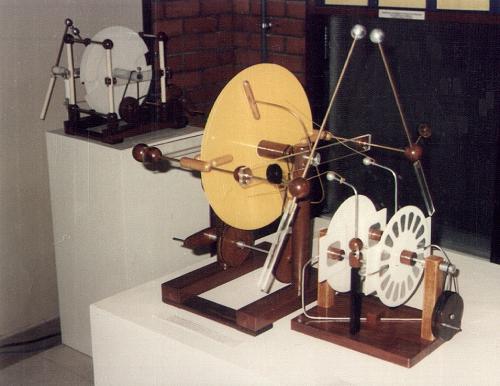
In February, 1999, I began tests with a large machine, with 37 cm disks, to better evaluate the performance of this machine. To reduce the size of the machine, and also to see what happens, I made the relative distance between the disks smaller. Some pictures of the machine: front, back, side, and other side views. The base and upright supports were built with 6 wood bars fixed with screws, The supports for the terminals/inductors were 1" PVC tubes fixed in nylon blocks. The inductors were solid wood cylinders, with spark shields glued at both ends. The other interconnections were made with wood balls, 1/4" brass bars, and 3/8" aluminum tubes. Connections inside the wood balls were improved with small springs. The terminal balls I made from aluminum flat sheets, by metal spinning technique in my lathe. I let the neutralizer circuit insulated from the ground by nylon blocks, to allow measurements and the insertion of loads in the circuit, as neon lamps. The two disks had 32 relatively small radial sectors made from adhesive aluminum tape.
The machine didn't show an impressive performance, considering its size. It self-excited easily, as the smaller machine, but sparks were limited to 14 cm of length (with one 2.3 cm ball at the positive terminal and a 3.8 cm ball at the negative. Long sparks were more easy to obtain from the smaller ball, positive, to the tube holding the negative terminal ball), and current was limited to 12 uA (measured at the neutralizer circuit), resulting in long intervals between sparks. Practically every large spark (with or without Leyden jars) discharged completely the inductors, and made the machine start again with opposite polarity.
The reasons for the poor performance were, however, simple to understand. The small distance between the disks and the vertical terminal supports caused sparks across the sectors of one disk, from a charge collector at one side to the support at the other side, jumping over a spark shield (total length 13.6 cm). This problem could be minimized with the vertical supports covered by insulators (I used plastic tubes), but not completely eliminated with spark shields of the size used. At least one of the terminals had to be covered, or corona between it and the sectors that had just passed at a neutralizer brush would drain most of the current. Identical terminal balls with 3.8 cm of diameter were too big for the maximum voltage that the machine could generate, and did not produce sparks at the limit. The current was small due to the small area of the disks covered by the sectors, and because it was difficult to turn the machine at high speed (required significant force). The maximum rotation speed that I could easily obtain was about 10.4 turns/second at the disks. Considering the area of the circular ring occupied by the sectors in one of the disks, 0.044 m2, and the maximum charge density in a surface in air, 26.5 uC/m2, the maximum current would be: 26.5 uC/m2 * 0.458 m2/s = 12.1 uA.
The machine could be improved with larger spark shields, longer and thinner sectors, greater distance between the disks, and more solidly built terminal assemblies. The reversals, with temporary loss of excitation at each spark, could probably be solved by the method used in a Voss machine, with inductors separated from the output circuit, but the mechanical disposition for this may be rather complicated in this machine.
The big machine was dismantled in February 2000, and some parts were reused in another project (the Triplex machine).
Created: 1997
Last update: 29 January 2015
By Antonio Carlos M. de Queiroz
Return to Electrostatic Machines