The Holtz Electrostatic Influence Machine
 The machine known as the "Holtz machine of the first kind" was the first
really powerful influence machine to be developed. It was invented by
Wilhelm Holtz, in Germany, and first described in 1865 [p33].
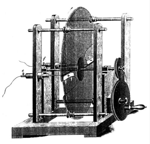
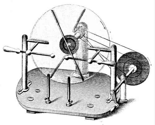
In the basic form, it consists of a rotating
disk in front of a fixed disk slightly larger. The fixed disk has two
paper plates (inductors) glued to it at diametrically opposite positions,
with one or more points that project through wide windows in the disk,
ending close to the back surface of the rotating disk, that turns in a
direction opposite to that points. In the front side of the rotating disk,
opposite to the inductors in the fixed plate, close to the pointed side of
them, two charge collectors with series of points collect charge from the
front surface of the rotating disk, and are connected to the terminals of
the machine. The original machine was
described in [p33].
The machine known as the "Holtz machine of the first kind" was the first
really powerful influence machine to be developed. It was invented by
Wilhelm Holtz, in Germany, and first described in 1865 [p33].
In the basic form, it consists of a rotating
disk in front of a fixed disk slightly larger. The fixed disk has two
paper plates (inductors) glued to it at diametrically opposite positions,
with one or more points that project through wide windows in the disk,
ending close to the back surface of the rotating disk, that turns in a
direction opposite to that points. In the front side of the rotating disk,
opposite to the inductors in the fixed plate, close to the pointed side of
them, two charge collectors with series of points collect charge from the
front surface of the rotating disk, and are connected to the terminals of
the machine. The original machine was
described in [p33].
To see how it works, assume that the disk is charged with negative charge
at the frontal surface at the left side of the machine (schematic,
with cylinders instead of disks). When it passes in front of the points
connected to the left inductor, negative charges are repelled from the
disk's back surface to the inductor, where they become concentrated in
front of the adjacent charge collector. When the disk passes in front of
the left charge collector, the negative charges in the disk are repelled
by the negative charges in the inductor to the output circuit, and the
disk leaves the charge collector with positive charge. The process is
repeated with inverted polarities at the other side. The charges in the
inductors increase exponentially, and the output voltage increases too,
until sparks occur at the terminals, or corona and losses limit the
voltage increase.
The machine built in this way requires constant current flow through the
output circuit to work. It must be started with the terminals
short-circuited, and if the terminals are separated beyond the maximum
sparking distance, it loses excitation, and can stop or revert polarity.
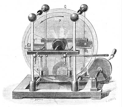
Holtz introduced the use of a "neutralizing rod"
to minimize this problem. This rod is a wire terminated in combs similar
to the charge collectors, positioned across the front disk, that acts as
an additional load positioned at an angle after the charge collectors. The
inductors are lengthened to cover an angle of 60-90 degrees, in order to
be also opposite to the ends of the neutralizing rod. It has no effect
while the load is conducting enough current, but prevents the loss of
excitation if the terminals are put too far apart, turning the machine
operation more stable. The original Holtz machine
with neutralizer [ p45] (1869).
Periodic polarity reversals occur easily, due to charge accumulation in
the inner side of the fixed disk, opposite to the inductor plates. This
charge eventually dominates over the charge in the inductors, reverting
the induction effect. As there are no brushes or metallic sectors, the
machine requires external excitation to start. It is enough to deposit
some charge in one of the inductor plates. The Holtz machine is similar to
the (more recent) Voss machine, but it doesn't
have sectors in the rotating disk and it's inductor plates collect charge
from the back of the rotating disk.
This machine had a fame of being difficult to start in humid weather, but
was considered one of the most powerful influence machines. Sparks with up
to 3/4 of the disk diameter were reported. Multiple
Holtz-type machines (This is the Holtz-Wimshurst machine [4]) were
extensively used as high voltage sources in early X-ray machines, due to
the high current output.
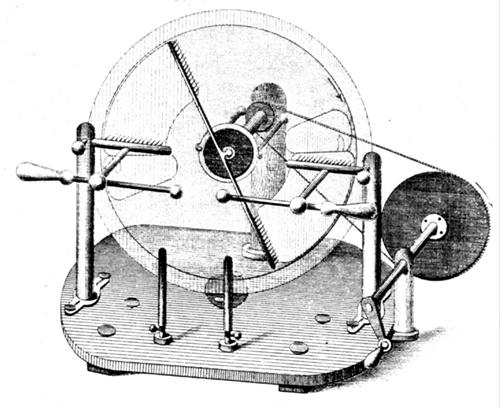
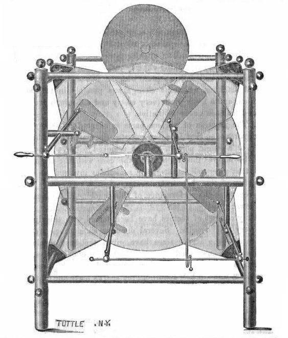
The Holtz machine can also be built with more than two inductor/collector
assemblies. A version with four inductors, built
by C. T. & J. N. Chester, that would produce twice more current at the
expense of some voltage, appears in [5]. The
picture is probably from [p105] (the
interconnection of the charge collectors is wrong. In this way the output
is short-circuited). It could be connected in several ways, including this [p127]
strange way with three charge collectors connected to one output and one
to the other. A similar machine [p125]
with the classical structure of the first publications by Holtz, that
could be connected in several ways, and a
version patented by the instrument builder
E. Ritchie [p128]. The idea of splitting the
fixed disk in several sections appears to
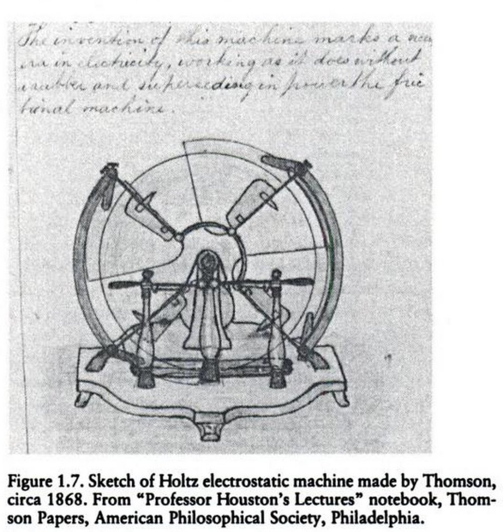
be due to H. Morton [p126]. This machine
(another picture, and see others here),
incomplete with the inductors and some connections missing, is another
implementation, as shown in this drawing
attributed to Elihu Thomson [67].
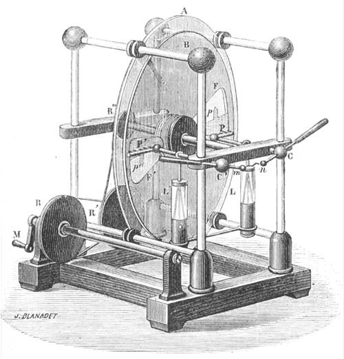
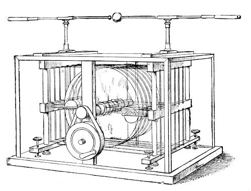
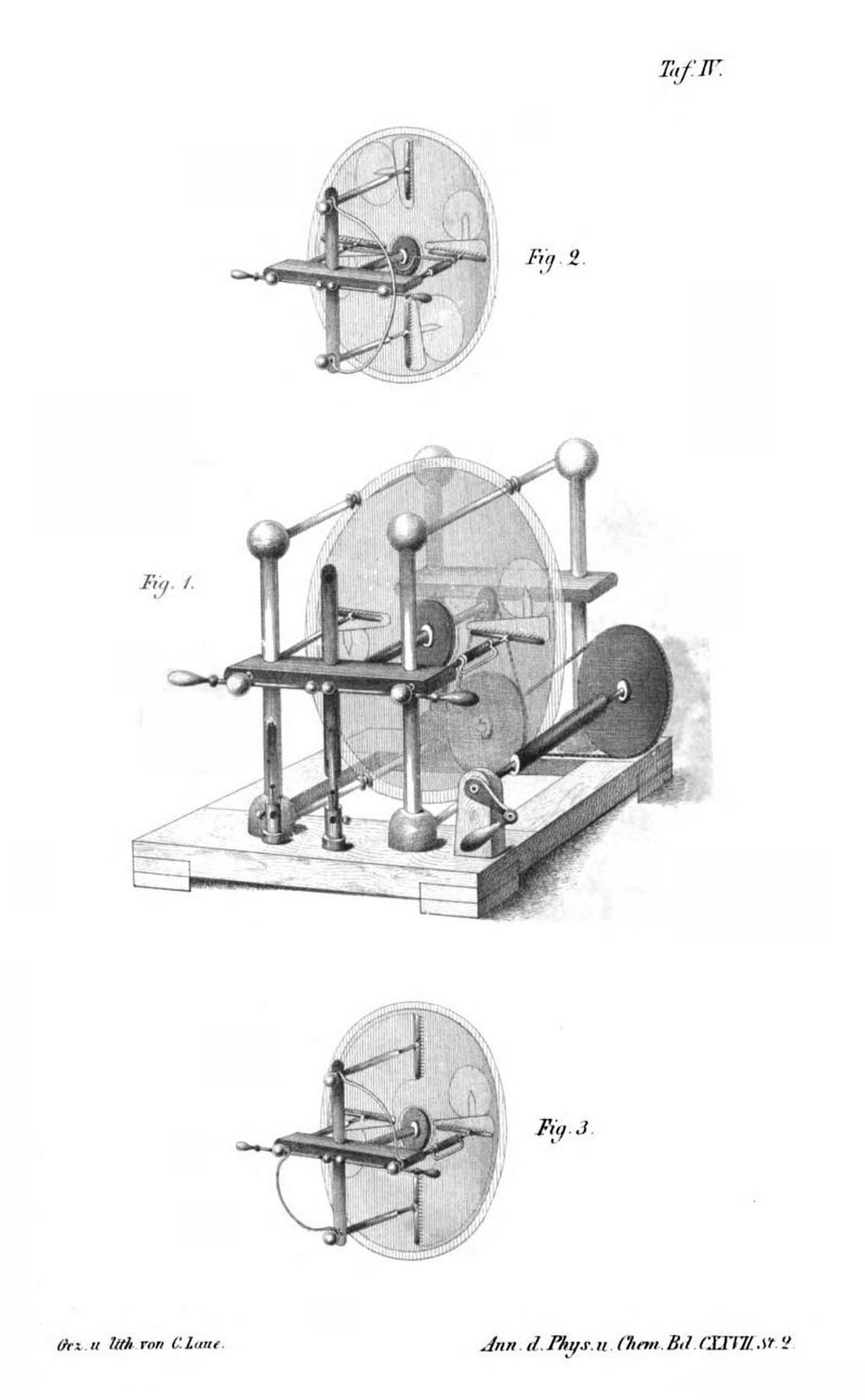
The Holtz machine of the second kind
This machine [p41]
(1867) consists of two parallel disks that rotate in opposite directions
at short distance, and four charge collector combs mounted in insulating
supports, two at opposite sides of the diameter of one disk, and two at
opposite sides of the perpendicular diameter of the other disk. The output
is taken between two separate sets of adjacent interconnected combs, as
shown. The machine can be seen as a basic Holtz machine where the plate
with inductors was replaced by another rotating disk. One disk serves as
inductor to the other, and vice-versa. The two outputs are combined to
double the output current. It is also equivalent to a Bonetti
machine (sectorless Wimshurst) where the charge collectors are removed and
the output taken in the middle of the neutralizer bars. It works as long
as there are sparks flowing, or a capacitor (Leyden jar) is being charged
between the terminals. In the original version
[24][p41], it had a fifth comb, later abandoned [p47]. Holtz experimented
also with a variation [p45]
(1869) of this design that is practically the Bonetti machine with output
taken at the front disk only (what gives to Holtz some priority in the
invention of that machine). The machine can have neutralizers too, to
allow operation with the output circuit open. In this case it's equivalent
to the Schaffers system (1885) for the Wimshurst
machine.
Many researchers studied the Holtz machines and variations. One of them
was Bleekrode [p95], that described experiments
with machines made with ebonite disks instead of glass disks in 1875.
Holtz himself wrote a long review paper in 1876 [p94].
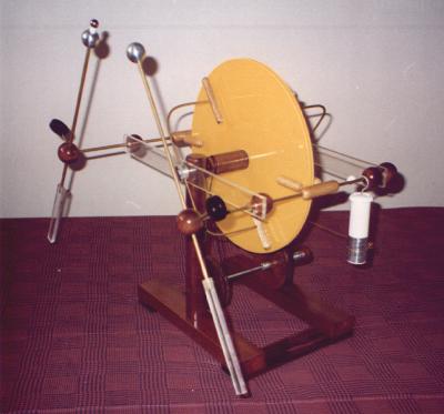
My Holtz machine - construction
In June 1997, I finished the construction of a Holtz
machine. It uses two white acrylic disks with 31 cm and 27.5 cm of
diameter. The support structure consists of a base made of wood bars, four
insulating supports made with 1.5 cm PVC tubes, acrylic bars supporting
the axle and the charge collectors, and brass bars insulated by plastic
tubes supporting the fixed disk. Wood pieces with various shapes and some
screws interconnect and fix these parts.
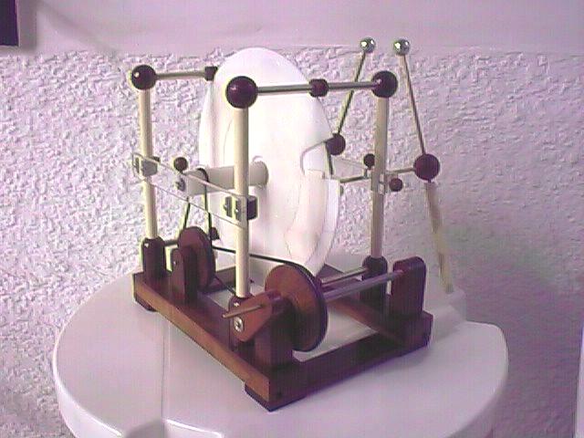
The design is similar to the one of most classic machines, but using
modern materials. The rotating disk is mounted in a nylon boss, and is
turned by a double pulley system connected to a crank, with a overall 10:1
turns ratio. The boss and the middle pulley are mounted on ball bearings.
The cords turning the pulleys are large rubber o-rings. The charge
collectors are made with serrated thick aluminum foil fixed in slits in
nylon rounded cylinders with a central aluminum rod. Brass bars insulated
by plastic tubes connect the collectors to the terminals, that can be
turned in (complicated and not very good) joints made of nylon and PVC.
The terminals are aluminum balls with 2.5 cm of diameter fixed to brass
bars that end in PVC tube handles. The neutralizer combs are identical to
the charge collectors, and are fixed to brass bars that are fixed to a
central aluminum piece in the axle. The neutralizer can be rotated to any
angle. The inductors are made of drawing paper, covering an angle of 60
degrees.
Operation of my Holtz machine
The machine is rather sensitive to humidity (as any machine without
metallic sectors), as has to be warmed with a hair dryer for some time
before operation in humid weather. To start the machine, it is enough to
apply some charge to one of the inductors. I do this by connecting a
sectored machine to one inductor, or by discharging a Leyden jar in one.
After the first start, it is easy to start it again while it retains some
charge by simply touching one of the inductors with the machine turning,
or moving the neutralizing rod to another position.
Without the neutralizer bar, the machine only works reliably when
connected to rather large Leyden jars (200 pF). With small load
capacitances it can start, but soon loses excitation. It enters a curious
cycle of rapid polarity reversals at about each 10 turns of the disk, and
reaches only moderately high voltage (3 cm sparks). Maybe I should have
tried smaller inductor plates, as the ones that I installed were larger
than the ones seen in pictures of classic machines. With the neutralizer
bar and longer inductors, it works even without capacitive load, takes
longer to revert polarity, and reaches higher voltages (8 cm sparks, with
a 9 mm ball glued to the positive terminal, separated by a short plastic
tube).
The machine works even with the output terminals short circuited, and
produces a rather high output current of about 37 uA. The voltage doesn't
increase more probably due to the accumulation of charge in the inner side
of the fixed disk. The collection of charge by the inductors generates
opposite charges exactly as the rotating disk passes under the inductors,
and part of this charge is attracted to the fixed disk. I am still
investigating some way to minimize this problem. The insulation of the
machine allows much higher voltages than I am obtaining. (But a spark
length of 1/4 of the disk diameter is not so bad. It is better than what
my Wimshurst machine produces, and the current
output is higher than in my Bonetti machine,
that uses larger disks.)
The periodical voltage reversals produce a beautiful display in the dark,
with many sparks covering the disks as the charges rearrange. I tried also
the use of metallic inductors, made of aluminum foil. They work as well as
the paper inductors, but in the dark it is apparent that the losses are
higher. The periodical polarity reversals occur at shorter intervals, and
the maximum spark length is somewhat reduced. My final design used paper
inductors with a metal strip under them. This turned the machine less
sensitive to humidity conditions and made it work more consistently.
The machine was built with the neutralizing bar insulated, and so can be
operated with one terminal grounded. With this the voltage at the other
terminal reaches almost twice the normal voltage. In this condition, the
light display in the dark is greatly enhanced, and (for some reason) the
maximum spark length is somewhat increased when the negative terminal is
grounded.
A different configuration:
By looking at the schematic diagram of the Holtz machine, it can be
observed that at the upper and lower quadrants, the rotating disk has
charges of equal polarities at both sides. If the neutralizer is rotated
so that it is above these areas, significant current flows through it. In
the other hand, the polarities of the charges in opposite sides of the
rotating disk are opposite when it passes in front of the charge
collectors, what reduces the induction effect.
Observing this, I rotated the fixed disk so that the inductors were at
the top and bottom quadrants, with the neutralizer in a vertical position,
acting as a short-circuit load, and the output being taken where the
voltage is maximum. This resulted in significantly higher voltages being
generated (11 cm sparks), although with smaller maximum current (16 uA).
I have found little reference to this possibility in old references,
although the design of the classical machines allowed this modification.
There is a hint about this idea in a paper by Holtz [p42]
(1867), and also brief comments in [27]. This
could be the reason for the holes in the fixed disk for the collectors
that feed the inductors, instead of simpler cuts in the sides of the
disks. With the fixed disk having a continuous border, it is simple to
rotate it to any position over its supports. The modification works better
if the inductors cover a small angle. I didn't try less than 60 degrees.
In January 2001, I modified the frontal bar that holds the charge
collectors and the axle, that had cracked. I fixed the conductors leading
to the terminals with screws (I replaced all the fixation screws for the
bars and the axle by similar screws made from 3/16" threaded rods and wood
balls), and modified the union between the conductors and the terminals by
wood balls, that have brass inserts where slotted plugs cut at the end of
the conductor bars can rotate. Front. Back.
See also the Wehrsen machine, that is an
improved version with embedded sectors in the rotating disk and a startup
system.
Last update: 29 December 2017
Created and maintained by Antonio Carlos M. de
Queiroz
Return to Electrostatic Machines