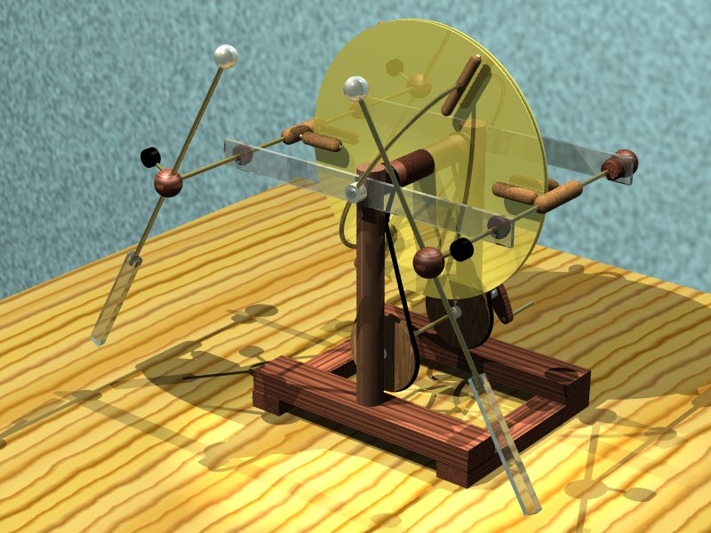
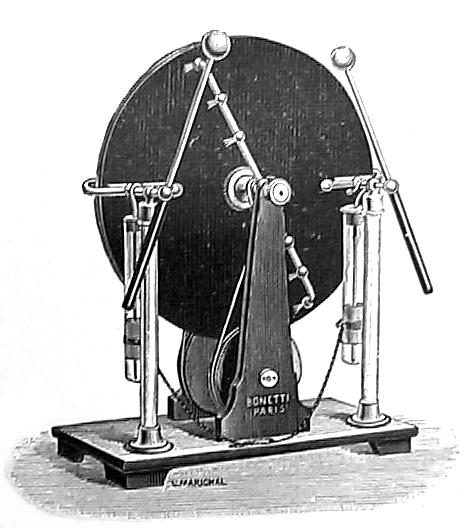
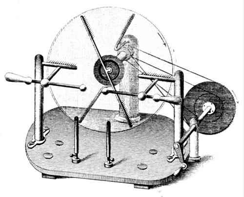
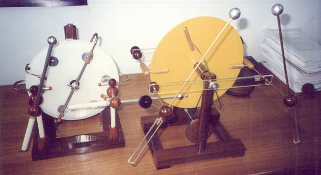
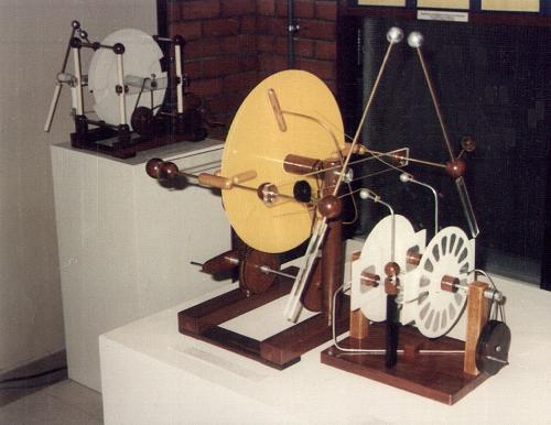
In March 1997, I built a sectorless Wimshurst machine, or Bonetti machine. This machine is identical to a Wimshurst machine, but uses bare disks, without metallic sectors, and the brushes in the neutralizer wires are replaced by combs, that do not touch the disks. The design was popularized by Louis Bonetti, an instrument maker in Paris, France, that proposed a similar machine based on the Wimshurst machine in 1894 [p78][p112], using sectorless disks and sets of several brushes in the neutralizer bars. The idea of a sectorless machine with essentially the same structure, however, can be traced back to Holtz and Poggendorff, by 1869 [p45][p47][p59][27], in this configuration, with output taken at the front disk only, combs instead of brushes in the neutralizer bars, and a different driving system. A machine with charge collectors at both sides, but previewing the disposition later discussed by Schaffers [p29] (with the charge collectors dislocated some degrees in the direction of the corresponding neutralizers) was studied by Musaeus, by 1872 [27][p47][29]. Also in 1894, Picolet [p79] described a sectorless machine using combs instead of brushes, built in 1892.
My machine uses acrylic disks with 31 cm of diameter, and is capable of producing sparks with up to 16.5 cm of length, between spheres with 3 cm of diameter.
The disks were cut from acrylic sheets 2 mm thick, with a tool made from a wood bar with handles and two screws attached, one filed to a shallow point and another to a cutting tool. A small hole is first made in the center, and the tool is used to cut deep grooves at both sides of the disk, with the pointed side resting in the hole. With the grooves deep enough, the disk can be detached easily from the sheet by breaking carefully the material. Remaining irregularity at the borders were removed with a file, and the disks were mounted, after enlargement of the central hole, in a motor (I used my lathe, attaching a screw with two nuts to the main axis through a wood bar, in the side opposite to the working area), and had the border filed and polished while turning at moderate speed (This method is rather dangerous and tricky. A better method is described in the restoration of a Ducretet and Roger Wimshurst machine, elsewhere in this site). The initial sheet must be perfectly flat and of uniform thickness.
The disks were mounted in bosses in the form of cylinders, made of hard wood, with a hole in the middle for the axis and recesses at both sides for ball bearings. A steel axis passes with good clearance through the central hole, and touches only the bearings, that are fixed by pressure in the wood bosses. The bosses are made by first making the central hole, mounting them in a steel bar, moistening the wood with water for a tight fit, and cutting the final form in a lathe. Grooves at one side are cut to receive the driving cords. The disks are fixed to the bosses by three flathead wood screws, with a layer of rubber between the disks and hubs. The right position for the disks is adjusted by adjusting the pressure of the screws. The spacing between the disks is controlled by fiber washers between them.
The pulleys that drive the bosses are made of wood, with a central aluminum hub that has a screw to fix the pulleys to the axis by pressure. The best way to make a pulley is to start from the middle, first making the hole in the aluminum hub, fixing it to the axis and shaping it in the lathe, and then adding a wood piece to the hub and shaping it in the lathe to the final form. The cords that connect the pulleys to the disk bosses are large rubber "O" rings. The pulleys are turned by a wood crank with an aluminum center identical to the ones in the pulleys.
The supporting structure is made of wood, with four bars making a base and two more making the uprights that support the disks. The pieces are fixed with wood screws. Holes are made in the uprights for the disks' axis, that doesn't turn, and for the driving pulley's axis, that turns, and is supported by ball bearings. The structure must be very solid, because the machine vibrates somewhat while running, due to irregularities in the disks (it may be necessary to balance the disks, by gluing small lead weights to the disks' borders, as I did).
The conductors are made of 3/16" brass bars. There are two, one at each side of the machine, supported by two plastic bars attached to the uprights. They are fixed to the bars by wood pieces, glued to the metal bars and screwed to the plastic supports. They terminate in wood balls, after crossing the bars. At one side, the balls support the machine terminals, made of brass bars, aluminum balls, and plastic handles. The position of the terminals is fixed by screws turning in nuts embedded in the wood balls. The threads of the screws are always well deep into the wood balls, to avoid losses.
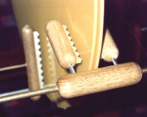
The charge collectors and the neutralizer combs are made of serrated aluminum foil (discardable pizza base), fixed in slits in rounded wood cylinders by aluminum wires inserted in holes across the center of the cylinders. This is very convenient, because the aluminum foil will never scratch the disks (or myself) in accidental touchings.
The neutralizer bars are made of 1/8" brass, bent to appropriate shape and fixed to the uprights by aluminum pieces that have screws to fix them in place. Screws pass through these pieces and the insulator bars, fixing everything firmly to the uprights, at the same height of the disks' axis.
The disks and insulators must be very clean and dry. They can be cleaned with alcohol or a furniture maintenance product based on carnauba wax (from times to times it is a good idea to wash the disks and insulators), and dried with a hot-air hair drier. The machine is started by another, self-exciting, machine, that has one terminal connected to a pointed wire, with the point close to a disk area opposite to one of the neutralizer combs (a ball terminal works too). The exciting machine is run for some seconds with the sectorless machine stopped, and them the machine is turned. This works almost always in dry weather, but can be difficult, or impossible, in humid days. A more effective procedure is to connect both terminals of a sectored influence machine to pointed wires held close to the areas opposite to two neutralizer combs in the same disk and do the same operation. The excitator machine can be removed after the startup procedure, or left in place, since the pointed wires extract little charge from the machine.
The excitation is perceived by a characteristic hissing noise and the ozone smell. Sparks start immediately to jump across the terminals, if they are not too far apart. In the dark, brush discharges can be seen flowing from the positive areas of the disks, and entirely covering the disk area between the negative charge collectors and the adjacent neutralizer combs.
Large, bright and noisy sparks are obtained with the addition of Leyden jars to the conductors. Two jars are used, one fixed to each conductor, with the outer armatures connected by a wire.
In dry weather, the machine starts by itself if stopped for a few seconds, or even minutes. In humid weather, it stops and has to be restarted by other machine, as described above. It can also lost excitation if the terminals are short-circuited, or one terminal grounded.
The addition of a smaller ball fixed to the positive terminal ball (I used a 9 mm steel ball, glued in place with the help of a short insulating tube), connected or not (better) to it, increases the frequency of the sparks, and can make them slightly longer. It is possible to add smaller balls to both terminals, to make the machine produce long sparks with any polarity. It is only necessary to arrange properly the terminals, with the best results being obtained with the two balls in the positive terminal aligned in the direction of the negative terminal's large ball. With only one small ball, the best results are obtained with the terminals in symmetrical position. The maximum voltage is, as in a Wimshurst machine, determined by the distance between the charge collectors and the adjacent neutralizer bars. In the Bonetti machine there are no sectors to decrease this distance, but the combs in the neutralizers produce brush discharges that travel easily to the collectors, and limit the maximum spark length at a value significantly shorter that the ideal, that would be about the double of the minimum collector-neutralizer distance.
The best conditions for the generation of long sparks are:
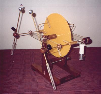
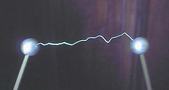
I have obtained 16.5 cm sparks, precisely the theoretic limit for the machine, with 200 pF jars, 3 cm terminal balls, and 70% air humidity. With small jars (50 pF, as in the pictures) or higher humidity, the spark length is limited to about 12-14 cm.
Last update: 30 December 2014
Antonio Carlos M. de Queiroz http://www.coe.ufrj.br/~acmq
Return to Electrostatic Machines